Balluff MICROPULSE BTL5 Series Technical Description, User's Manual
Micropulse linear position sensor
Hide thumbs
Also See for MICROPULSE BTL5 Series:
- User manual (4 pages) ,
- User manual (94 pages) ,
- Condensed manual (12 pages)

Related Manuals for Balluff MICROPULSE BTL5 Series


Summary of Contents for Balluff MICROPULSE BTL5 Series
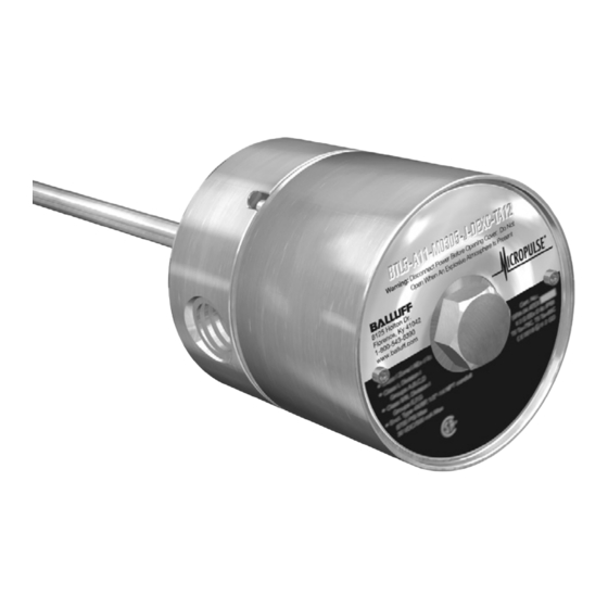
- Page 1 Technical Description / User’s Guide BTL5-_-M_-J-DEXC-TA12 Micropulse Linear Position Sensor Analog & Digital-Pulse Outputs Explosion-Proof (Flame-Proof) Rod Style...
-
Page 2: Table Of Contents
Severity level 3 Electromagnetic fields (RFI) In our accredited EMC Laboratory, proof has EN 61000-4-3 Severity level 3 been documented that these Balluff products Fast transients (Burst) meet the EMC requirements of the following EN 61000-4-4 Severity level 3 product standard:... -
Page 3: Preface - Atex Directive Instructions
European equivalent 1.4404, 1.4571, 1.4305) • Viton (used for O-ring seals) If the equipment is likely to come into contact with aggressive substances, then it is the responsibility of the user to take suitable precautions that prevent it www.balluff.com • 1-800-543-8390... -
Page 4: Introduction
Read this manual before installing the Micropulse EX linear position sensor. The Micropulse EX linear position sensor should be installed by qualified personnel and used in accordance with the conditions for which it was designed. Any unauthorized modification could result in equipment damage or personal injury, and is expressly forbidden. 1-800-543-8390 • www.balluff.com... -
Page 5: Approvals
An internal electronics module/sensing element that provides electrical position feedback signals in the form of an analog voltage, analog current, or digital pulse signals. The internal electronics module/sensing element can be replaced while the external housing stays in place. www.balluff.com • 1-800-543-8390... -
Page 6: Component Overview
12. Flange O-Ring (not visible). 13. External Housing GND. 14. Internal Housing GND. 15. 1/2”-14 NPT-to-M20 Adapter (optional). See section 5.2 for additional information. 16. Cover secondary retaining screw. 17. Location of order code for replacement electronics module. 1-800-543-8390 • www.balluff.com... - Page 7 BTL5-_-M_-J-DEXC-TA12 Micropulse Linear Position Sensor Analog & Digital-Pulse Outputs Explosion-Proof Rod Style Product Label (detail, example) 1) Order code forcomplete linear position sensor assembly 2) Type 3) Serial number 4) Production location www.balluff.com • 1-800-543-8390...
-
Page 8: Mechanical Data
BTL5-_-M_-J-DEXC-TA12 Micropulse Linear Position Sensor Analog & Digital-Pulse Outputs Explosion-Proof Rod Style 4 Mechanical Data 4.1 Dimensions 1-800-543-8390 • www.balluff.com... -
Page 9: Specifications
BTL5-_-M_-J-DEXC-TA12 Micropulse Linear Position Sensor Analog & Digital-Pulse Outputs Explosion-Proof Rod Style 4.2 Specifications www.balluff.com • 1-800-543-8390... -
Page 10: Accessories
Class I Division 1 & 2, Groups A, B, C, D I M2, II 2 GD Class II & III, Groups E, F, G Dia.15 26.80 21.85 ½” NPT Threads Dia.15 Top View 21.85 ½” NPT Threads M20 Threads 18.40 1-800-543-8390 • www.balluff.com... -
Page 11: Floats
Part number BTL2-S-4414-4Z01-EX BTL2-S-4414-4Z-EX Material Stainless 316 Stainless 316 Weight 52 g 34 g Minimum fluid density 0.85 g/cm 0.7 g/cm Immersion depth in 1 g/cm 45 mm 30 mm Immersion depth in 0.7 g/cm Sinks 39 mm www.balluff.com • 1-800-543-8390... -
Page 12: Installation Instructions
Tighten secondary retaining screw (ATEX). Fig. 1 Fig. 2 6.2 Installation in Hydraulic/Pneumatic Cylinders If the linear position sensor is to be installed in a cylinder, prepare the cylinder port in accordance with the diagram below. thru-hole Bevel for O-Ring 15.4x2.1 1-800-543-8390 • www.balluff.com... -
Page 13: Installing In Zone 0 Locations
Pwr Supply (+10 to +30 Vdc) Pwr Supply (+24V) Output Channel B (-) CAN GND Output Channel Z (+) CAN Low Output Channel Z (-) CAN High Strobe Input Not used Typical housing with Not used Not used terminal block assembly. www.balluff.com • 1-800-543-8390... -
Page 14: Using Analog Programming Tool
Attention! Attention! Replacement parts must be obtained Les pièces de rechange doivent from Balluff to ensure that the product proveni de Balluf pour s'assurer que la certification is not invalidated. certification de produit n'est pas invalidée Step 1: Disconnect power source. -
Page 15: Order Code
BTL5-T1_ 0-M _ _ _ _-J-DEXC-TA12 (complete linear position sensor) Software configuration Standard nominal stroke [mm] Connection 1 × position and 0025...3962 mm TA12 Internal thread modified 1 × velocity 1/2" 14 NPT 2 × position and 2 × velocity www.balluff.com • 1-800-543-8390... - Page 16 Phone: (905) 816-1494 Toll-free: 1-800-927-9654 Fax: (905) 816-1411 Web: www.balluff.ca E-mail: balluff.canada@balluff.ca Mexico Balluff de Mexico SA de CV Anillo Vial II Fray Junipero Serra No. 4416 Colonia La Vista Residencial Queretaro, QRO CP76146 Phone: (++52 442) 212-4882 Fax: (++52 442) 214-0536 Web: www.balluff.mx...
Need help?
Do you have a question about the MICROPULSE BTL5 Series and is the answer not in the manual?
Questions and answers