Table of Contents
Advertisement
Quick Links
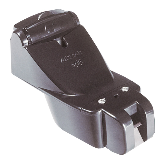
OWNER' S GUIDE
Transom-mount Depth Transducer
or TRIDUCER
U. S. Patents: 5,606,253; 5,719,824
WARNING: Always wear safety goggles and a dust
mask when installing to avoid personal injury.
CAUTION: Never use solvents. Cleaners, fuel,
sealants, paint, and other products may contain strong
solvents, such as acetone, which attack many
plastics, greatly reducing their strength.
IMPORTANT: Read the instructions completely
before proceeding with the installation. These
instructions supersede any other instructions in your
instrument manual if they differ.
Applications
• Not recommended for boats with large or twin-screw inboard
engine(s)
• Not recommended for stepped hulls
• Good operation up to 44kn (50MPH)
• Vertically orients sound beam on hull with deadrise angle up to 30°
• Adjusts to transom angles from 2
• Bracket protects sensor from frontal impact only
Tools & Materials
Safety goggles
Dust mask
Scissors
Masking tape
Electric drill
Drill bits:
Bracket holes
Transom hole (optional)
Cable clamp holes
Angle finder
Marine sealant
Screwdrivers
Straight edge
Pencil
Grommet(s) (some installations)
Cable ties
Water-based anti-fouling paint (mandatory in salt water)
Figure 1. Headroom required on a stepped transom
Copyright © 2003 Airmar Technology Corp.
Multisensor
®
with Integral Release Bracket
Model P66
°
°
–22
4mm, #23, or 9/64"
21mm or 13/16"
3mm or 1/8"
min.: 127mm (5")
max. no speed sensor:
headroom
191mm (7-1/2")
max. with speed sensor:
213mm (8-1/2")
&
Installation INSTRUCTIONS
Record the information found on the cable tag for future reference.
Part No._________________Date___________Frequency________kHz
Transducer
Pretest Speed & Temperature Functions
Connect the multisensor to the instrument and spin the
paddlewheel. Check for a speed reading and the approximate air
temperature. If there is no reading(s) or it is inaccurate, return the
product to your place of purchase.
Mounting Location
CAUTION: Do not mount in an area of turbulence or bubbles.
Near water intake or discharge openings
Behind strakes, struts, fittings, or hull irregularities
CAUTION: Avoid mounting the sensor where the boat may be
supported during trailering, launching, hauling, or storage.
• For the best performance, the sensor must be in contact with
smooth water. To identify an area of clean water, observe the
water flow off the transom while the boat is underway.
• Allow headroom space above the bracket for it to release and
rotate the sensor upward (see Figure 1).
• Mount the sensor as close to the centerline (keel) of the boat as
possible to ensure the transducer's face remains in the water
when the boat is turning.
• Single drive boat—Mount at least 75mm (3") beyond the
swing radius of the propeller (see Figure 2). The starboard side
where the propeller blades are moving downward is preferred.
• Twin drive boat—Mount the sensor between the drives.
Figure 2. Mounting location on single drive boat
NOTE: Starboard
side of hull where
propeller blades are
moving downward is
preferred.
75 mm (3")
minimum beyond
swing radius
Copyright © 2003 Airmar Technology Corp.
TRIDUCER
®
multisensor
Advertisement
Table of Contents

Related Manuals for Airmar TRIDUCER P66


Summary of Contents for Airmar TRIDUCER P66
- Page 1 75 mm (3") max. with speed sensor: minimum beyond 213mm (8-1/2") swing radius Figure 2. Mounting location on single drive boat Figure 1. Headroom required on a stepped transom Copyright © 2003 Airmar Technology Corp. Copyright © 2003 Airmar Technology Corp.
- Page 2 2. Using the vertical adjustment space on the bracket slots, slide the bracket up or down until the distance between the bottom left corner and the bottom Figure 4. Template position of the transom equals 38mm (1-1/2"). Tighten the screws. Copyright © 2003 Airmar Technology Corp. bracket self-tapping closed...
- Page 3 Figure 10. Sensor angle adjustment sensor or parallel to the bottom of the hull. Copyright © 2003 , 2010 Airmar Technology Corp. 2. Check that the bottom left corner of the sensor projections 3mm (1/8") below the bottom of the hull (see Figure 11).
- Page 4 CAUTION: Do not remove the connector to ease cable routing. If the cable Clean the transducer’s surface with a Scotch-Brite® scour pad and mild must be cut and spliced, use Airmar’s splash-proof Junction Box No. 33-035 household detergent taking care to avoid making scratches. If the fouling and follow the instructions provided.
Need help?
Do you have a question about the TRIDUCER P66 and is the answer not in the manual?
Questions and answers