Table of Contents
Advertisement
Quick Links
OWNER' S GUIDE & INSTALLATION INSTRUCTIONS
Transom Mount Transducer
or TRIDUCER
®
U. S. Patents: 4,555,938; 4,644,787; 5,606,253; Des. 334,335
Canadian Patent 1,233,341
IMPORTANT : Please read the instructions completely
before proceeding with the installation. These
instructions supersede any other instructions in your
instrument manual if they differ.
CAUTION : NEVER USE SOLVENTS
Cleaners, fuel, paint, sealants, and other products may
contain strong solvents, such as acetone, which attack
many plastics greatly reducing their strength.
Applications
• Not recommended for boats with large or twin screw inboard
engine(s).
• Good operation up to 44kn (50MPH)
• Vertically orients sound beam on hull with deadrise angle up to 30°
• Adjusts to transom angles from 2
• Bracket protects sensor from frontal impact only
Tools and Materials
Pencil
Safety goggles
Dust mask
Electric drill
Drill bits:
Bracket holes
Fiberglass hull
Transom hole (optional) 20mm or 13/16"
Cable clamp holes
Masking tape
Marine sealant
Screwdrivers
Straight edge
Zip-ties
Water-based antifouling paint ( mandatory in salt water )
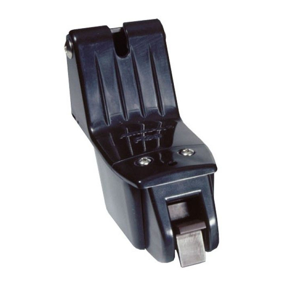
Headroom without
speed sensor
109mm (4-5/16")
Headroom with
speed sensor
130mm (5-1/8")
Figure 1. Headroom required at mounting location
Multisensor
with Integral Release Bracket
Model P39
°
°
–22
4mm, #23, or 9/64"
chamfer, countersink, 6mm, or 1/4"
3mm or 1/8"
headroom
Record the information found on the cable tag for future reference.
Part No._________________Date___________Frequency________kHz
Pretest
Connect the sensor to the instrument and spin the paddlewheel.
Check for a speed reading (and the approximate air temperature if
applicable). If there is no reading or it is inaccurate, return the
instrument to your place of purchase.
Mounting Location
To ensure the best performance, the sensor must be in contact
with aeration-free and turbulence-free water. Mount the sensor on
the transom as close to the centerline (keel) of the boat as
possible. On slower heavier displacement hulls, positioning it
farther from the centerline is acceptable.
Headroom —Allow adequate space above the bracket for it to
release and rotate the sensor upward (see Figure 1).
Caution : Do not mount in an area of turbulence or bubbles:
Near water intake or discharge openings;
Behind strakes, struts, fittings, or hull irregularities;
Behind eroding paint (an indication of turbulence).
Caution : Avoid mounting the sensor where the boat may be
supported during trailering, launching, hauling, or storage.
• Single drive
boat —Mount
the sensor on
the starboard
side at least
75mm (3")
beyond the
swing radius of
the propeller
(see Figure 2).
• Twin drive
boat —Mount
the sensor
between the
drives.
P39
TRIDUCER ®
multisensor
75 mm (3")
minimum beyond
swing radius
Figure 2. Mounting location
on single drive boat
Advertisement
Table of Contents

Related Manuals for Airmar TRIDUCER P39


Summary of Contents for Airmar TRIDUCER P39
- Page 1 OWNER’ S GUIDE & INSTALLATION INSTRUCTIONS Transom Mount Transducer Record the information found on the cable tag for future reference. or TRIDUCER Multisensor ® Part No._________________Date___________Frequency________kHz with Integral Release Bracket Model P39 U. S. Patents: 4,555,938; 4,644,787; 5,606,253; Des. 334,335 Canadian Patent 1,233,341 IMPORTANT : Please read the instructions completely before proceeding with the installation.
- Page 2 Plastic Shim • Standard transom (13° transom angle)—The bracket is designed for a standard 13° transom angle. The shim is not pivot post (2) needed for this installation. Skip to “Mounting the Bracket”. • Stepped transom and jet boats (3° transom angle) —Use the shim with the tapered end down .
- Page 3 Warning : Always wear safety goggles and a dust mask. 13 ° transom angle 3 ° transom angle 20 ° transom angle 1. If a hole must be drilled through the transom, choose a location well above the waterline (see Figure 4). Check for obstructions such as trim tabs, pumps, or wiring inside the hull.
- Page 4 In severe cases, wet sand the paddlewheel with Figure 9. Servicing the speed sensor fine grade wet/dry paper. AIRMAR 35 Meadowbrook Drive, Milford, New Hampshire 03055-4613, USA TECHNOLOGY CORPORATION www.airmar.com ■...
Need help?
Do you have a question about the TRIDUCER P39 and is the answer not in the manual?
Questions and answers