Advertisement
Quick Links
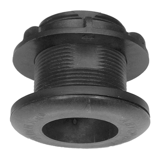
OWNER' S GUIDE
Shorty
Thru-Hull Depth Transducer
™
Low Profile, Flush, and Retractable Models:
P6, P7, P8, P206, P207, and P208
IMPORTANT : Please read the instructions completely
before proceeding with the installation. These
instructions supersede any other instructions in your
instrument manual if they differ.
CAUTION : NEVER USE SOLVENTS!
Cleaners, fuel, paint, sealants, and other products can
contain strong solvents, such as acetone, which attack
many plastics greatly reducing their strength.
Applications
• Recommended for fiberglass or metal hulls only
• Never install a plastic thru-hull housing in a wood hull, since
swelling of the wood can possibly fracture the plastic.
• Low profile housing recommended for cruising sailboats and
planing hull powerboats
• Flush housing recommended for racing sailboats and high-
speed powerboats
• Hull deadrise angle should not exceed 20º
Tools & Materials
Safety goggles
Dust mask
Electric drill with minimum 10mm (3/8") chuck capacity
Drill bit
Hole saw
Countersink tool (installing P206, P207, P208 flush housings)
Sandpaper
Mild household detergent or weak solvent (such as alcohol)
File (installation in a metal hull)
Marine sealant (suitable for below waterline)
Additional washer [aluminum hull less than 6mm (1/4") thick]
Zip-ties
Water-based antifouling paint ( mandatory in salt water )
Installation in a cored fiberglass hull (see page 3):
Hole saw for hull interior
Fiberglass cloth and resin
or Cylinder, wax, tape, and casting epoxy
Identify Your Model
The model name is printed on the cable tag.
3mm or 1/8"
51mm or 2"
60mm or 2-3/8"
&
INSTALLATION INSTRUCTIONS
Record the information found on the cable tag for future reference.
Part No._________________Date___________Frequency________kHz
P6, P7
Low profile
Hull Thickness
Model
P6, P7 (low profile)
P8 (low profile, retractable)
P206, P207 (flush)
P208 (flush, retractable)
Mounting Location
Placement
Choose a location:
• Where the transducer will be continuously immersed in water.
• Where the water flowing across the hull is smoothest with a
minimum of bubbles and turbulence (especially at high speeds).
• Where the transducer beam will be unobstructed by the keel or
propeller shaft(s).
• Away from interference caused by power and radiation sources
such as: the propeller(s) and shaft(s), other machinery, other
echosounders, and other cables. The lower the noise level, the
higher the echosounder gain setting that can be used.
• Where there is a minimum deadrise angle, not exceeding 20º,
so the transducer beam will be aimed toward the bottom.
• Where there is adequate headroom inside the vessel for the height
of the housing, tightening the nuts, and removing any insert.
Model
P6, P7, P206, P207
Retractable P8, P208
Caution : Do not mount in an area of turbulence or bubbles:
near water intake or discharge openings;
behind strakes, fittings, or hull irregularities.
P8
Low profile, retractable
Minimum
Maximum
1
6mm (
⁄
")
38mm (1
4
1
6mm (
⁄
")
25mm (1")
4
7
11mm (
⁄
")
43mm (1
16
7
11mm (
⁄
")
30mm (1
16
Minimum Headroom
76mm (3")
153mm (6")
1
⁄
")
2
3
⁄
")
4
3
⁄
")
16
Advertisement

Related Manuals for Airmar Shorty P6


Summary of Contents for Airmar Shorty P6
- Page 1 OWNER’ S GUIDE & INSTALLATION INSTRUCTIONS Shorty Thru-Hull Depth Transducer Record the information found on the cable tag for future reference. ™ Part No._________________Date___________Frequency________kHz Low Profile, Flush, and Retractable Models: P6, P7, P8, P206, P207, and P208 IMPORTANT : Please read the instructions completely before proceeding with the installation.
- Page 2 (see Figure 2). This will ensure there is sealant in the threads to seal the hull and hold the hull nut securely in place. Installing AIRMAR ® 1. From outside the hull, push the housing (and cable if applicable) into the mounting hole using a twisting motion to squeeze out pressure waves excess sealant.
- Page 3 24 hours. If a leak is observed, repeat “Bedding” and the instructions provided. Cutting the cable or removing the “Installing” immediately (see page 2). connector, except when using Airmar’s junction box, will void the transducer warranty. Antifouling Paint 1. Route the cable to the instrument, being careful not to tear the...
- Page 4 Retractable models are furnished with a blanking plug which should be used when the boat will be kept in salt water for more The information needed to order a replacement Airmar transducer is than a week, the boat will be removed from the water, or aquatic printed on the cable tag.
Need help?
Do you have a question about the Shorty P6 and is the answer not in the manual?
Questions and answers