Table of Contents
Advertisement
Quick Links
Advertisement
Table of Contents

Related Manuals for Madas FRG/2MCS9


Summary of Contents for Madas FRG/2MCS9
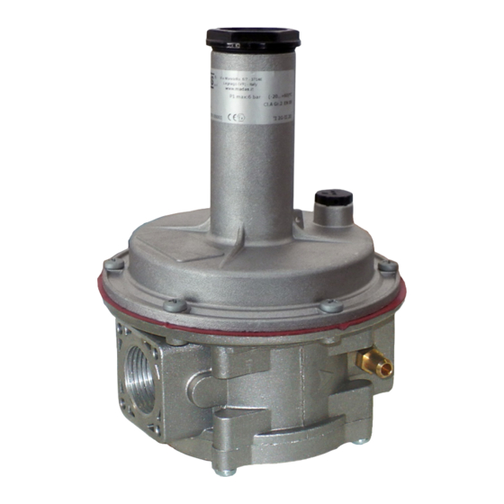
- Page 1 GAS PRESSURE REGULATOR FRG-RG/2MCS9 Pe: 0,5 ÷ 9 bar DN15 - DN 20 - DN 25...
- Page 2 INDEX pag. English ................................3 Drawings ..............................10 Flow data (table 1) .............................. 13 Dimensions (table 2) .............................14 Regulation spring data (table 3) ........................15...
-
Page 3: General Information
1.0 - GENERAL INFORMATION This manual shows you how to safely install, operate and use the device. The instructions for use ALWAYS need to be available in the facility where the device is installed. ATTENTION: installation/maintenance needs to be carried out by qualified staff (as explained in section 1.3) by using suitable personal protective equipment (PPE). -
Page 4: Technical Data
• Flanged connections that can couple with PN 16 flanges : on request DN 25 with swivel flanges • Standard filter element : filtering 50µm (on FRG... versions) 2.1 - MODEL IDENTIFICATION FRG/2MCS9: Pressure regulator with filter - Standard version RG/2MCS9: Pressure regulator without filter - Standard version 3.0 - COMMISSIONING THE DEVICE 3.1 - OPERATIONS PRIOR TO INSTALLATION... - Page 5 If the device is threaded: make sure that the pipe thread is not too long, to prevent damaging the body of the device when screwing it on; If the device is flanged: • make sure the inlet and outlet counter-flanges are perfectly coaxial and parallel in order to prevent unnecessary mechanical stress to the body.
- Page 6 1. Expansion joint/anti-vibration mount 5. Vent valve 2. Upstream ball valve 6. Relief valve MVS/1 3. FRG/2MCS9 pressure regulator filter 7. Low pressure gauge and relative button 4. Ball valve downstream of the regulator 8. High pressure gauge and relative button...
-
Page 7: First Start-Up
4.0 - FIRST START-UP Before commissioning, verify that: • all of the instructions on the rating plate, including the direction of flow, are observed; • the hole of the dust cap (18) is not clogged; • IMPORTANT: The leak test of the piping must be performed without subjecting the diaphragm of the regulator (therefore, the downstream pipe section) to a pressure higher than 300 mbar (for reinforced diaphragm 1.5 times the regulator setting pressure). -
Page 8: Recommended Periodic Checks
5.2 - Adjusting the outlet pressure (Pa) The outlet pressure Pa (unless specifically requested) is factory-set with the regulator installed as indicated in 3.4 and with the adjustment screw (2) set approximately at the minimum setting value. The relief valve is set accordingly. If the regulator is installed in different positions, check and reset the outlet pressure Pa, and consequently the devices incorporated in the regulator;... -
Page 9: Warranty
The warranty also excludes maintenance work, the assembly of parts or non-original spare parts, making changes to the device and natural wear. 10.0 - RATING PLATE DATA Via Moratello, 5/7 - 37045 Legnago (VR) - Italy www.madas.it Mod.: FRG/2MCS9 DN 25 PS=Pe:0,5-9 bar (-20...+60)°C Pa: 300-650 mbar DfRv:40-200 mbar AC10 SG10 year: 2018... - Page 10 1 For relief FRG/2MCS9 - RG 2MCS9 Top part of the regulator with relief valve valve setting G 1/4...
- Page 11 2 FRG/2MCS9 RG/2MCS9 RG-FRG/2MCS9... DN 15 - DN 20 - DN 25 Required tool for setting Pa with relief without relief 13mm Top part of the regulator with or without relief valve...
- Page 12 fig. 1 and 2 1. Closing cap 2. Pa adjustment screw 3. Top cover 4. Pa Setting spring 5. Top disk for diaphragm 6. Top cover clamping screws 7. Compensation diaphragm 8. Filter element (only on FRG...) 9. Bottom 10. Bottom fastening screws 11.
- Page 13 Table 1 Flow data (m /h gas) P2 (mbar) (bar) 1000 1400 1800 2000 2500 3000 = 0,806 Natural Gas Town gas = 1.177 = 0.62...
- Page 14 Table 2 Overall dimensions in mm Threaded Flanged RG-FRG/2MCS9... connections connections DN 15 - DN 20 - DN 25 DN 25 The dimensions are provided as a guideline, they are not binding...
- Page 15 Table 3 REGULATION SPRINGS DATA FRG/2MCS9 - RG/2MCS9 DN 15 - DN 20 - DN 25 Pa Setting springs dimensions in mm Range Spring code (mbar) (d x De x Lo x it) 170 ÷ 400* MO-1320 3,5x29,8x64x9 300 ÷ 650*...
- Page 16 We reserve the right to any technical and construction changes. Sede legale: Via V. Moratello, 5/6/7 - 37045 Z.A.I. Legnago (VR) Italy Unità locale: Via M. Hack, 1/3/5 - 37045 Z.A.I. Legnago (VR) Italy Tel. +39 0442/23289 - Fax +39 0442/27821 - http://www.madas.it - e-mail: info@madas.it...
Need help?
Do you have a question about the FRG/2MCS9 and is the answer not in the manual?
Questions and answers