Sign In
Upload
Download
Table of Contents
Contents
Add to my manuals
Delete from my manuals
Share
URL of this page:
HTML Link:
Bookmark this page
Add
Manual will be automatically added to "My Manuals"
Print this page
×
Bookmark added
×
Added to my manuals
Manuals
Brands
jotron Manuals
Radio
TR-7750C
Operator's manual
jotron TR-7750C Operator's Manual
Vhf maritime communication radios
Hide thumbs
1
2
3
4
5
6
7
Table Of Contents
8
9
10
11
12
13
14
15
16
17
18
19
20
21
22
23
24
25
26
27
28
29
30
31
32
33
34
35
36
37
38
39
40
41
42
43
44
45
46
47
48
49
50
51
52
53
54
55
56
57
58
59
60
61
62
63
64
65
66
67
68
69
70
71
72
73
74
75
76
77
78
79
80
81
82
83
84
85
86
87
88
page
of
88
Go
/
88
Contents
Table of Contents
Bookmarks
Table of Contents
Table of Contents
1 Introduction
Models Covered by this Manual
Layout of the Transceiver
Applications
2 Technical Specifications
General Specification, Transceiver Units, TR-7750C
Transmitter Units, TA-7650C
Receiver Unit, RA-7203C
Power Supply Unit, PSU-7002
3 Functional Description
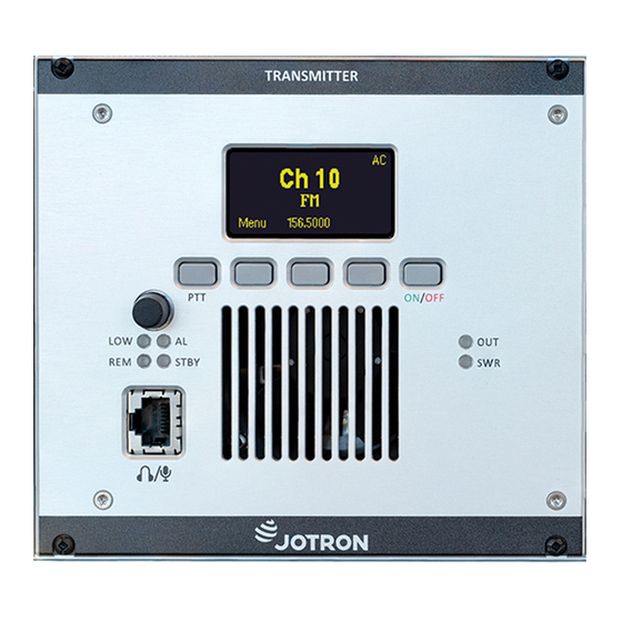
Front Panel Controls, Transmitter Unit
Display
Scroll/Select Switch and Navigation Buttons A, B and C
PTT Button
ON/OFF Button
LED Indicators
MIC/Headset Connector
Transmitter, Rear Connections
Antenna Connector (50 Ohm N)
Receiver Ant. Connector (50 Ohm BNC)
DC Input Connector (Amphenol MS 3106A 10SL4S)(Jotron P/N: 96715)
LAN Connector (RJ45)
Aux1 Connector (Rj45)
AUX2 Connector (RJ45)
REM Connector (RJ45)
Rx Connector (RJ45)
Front Panel Controls, Receiver Unit
Display
Scroll/Select Switch and Navigation Buttons A, B and C
ON/OFF Button
LED Indicators
Headset Connector
Receiver, Rear Connections
Antenna Connector (50 Ohm N)
DC Input Connector (Amphenol MS 3106A 10SL4S)(Jotron P/N: 96715)
LAN Connector (RJ45)
Aux1 Connector (Rj45)
AUX2 Connector (RJ45)
REM Connector (RJ45)
PSU-7002, Power Supply Unit, Frontview
LED Indicators
Power Supply Unit Rear Connectors
DC Input Connector (Amphenol MS 3106A 10SL4S)(Jotron P/N: 96715)
DC Output Connector(Amphenol MS 3106A 12S3P)(Jotron P/N: 93697)
AC Input Connector
4 Installation
Introduction
Initial Inspection
Installation into Equipment Cabinet
Antenna Connectors
Ac and DC Connectors
Remote Signals
REM Connector (Receiver) and RX Connector (Transmitter)
Audio In/Out and Line Loop Keying
Other Key Signals
Squelch and AGC Signals, Receiver Unit
Alarm and Select Signals Transmitter and Receiver
Miscellaneous Signals, Transmitter
Applications
Transceiver, Local Configuration
Transceiver, Remote Configuration
Transmitter, Main / Backup Configuration
Receiver, Main / Backup Configuration
5 Operating Instructions
Introduction
User Menu - Transmitter (Restricted Access Level)
User Menu - Transmitter (Default Access Level)
Setting, Information and Configuration Menus - Transmitter
Radio Control Group
TX Config Group
Interface Config Group
Bite System Group
System Info Group
Parameter Details - Transmitter
Radio Control Group
TX Config Group
Interface Config Group
Bite System Group
User Menu - Receiver (Restricted Access Level)
User Menu - Receiver (Default Access Level)
Setting, Information and Configuration Menus - Receiver
Radio Control Group
RX Config Group
Interface Config Group
Bite System Group
System Info Group
Parameter Details - Receiver
Radio Control Group
RX Config Group
Interface Config Group
Bite System Group
6 Error Conditions and Corrective Actions
Transmitter Error Conditions
Receiver Error Conditions
7 List of Tables and Figures
Appendix A. List of Maritime Channels and Frequencies
Advertisement
Quick Links
1
General Specification, Transceiver Units, Tr-7750C
2
Transmitter Units, Ta-7650C
Download this manual
Table of
Contents
Previous
Page
Next
Page
1
2
3
4
5
Advertisement
Table of Contents
Need help?
Do you have a question about the TR-7750C and is the answer not in the manual?
Ask a question
Questions and answers
Related Manuals for jotron TR-7750C
Transmitter jotron TA-7650C Maintenance And Repair Manual
Maritime vhf transmitter (26 pages)
Radio jotron TR-810 Operator And Installation Manual
Vhf am ground to air communication radio (32 pages)
Radio jotron TRON TR20 PLUS User Manual
Handheld (50 pages)
Radio jotron TRON TR20 GMDSS User Manual
(52 pages)
Radio jotron Tron TR30 User Manual
(81 pages)
Radio jotron Tron TR30 User Manual
Vhf gmdss & vhf radio with charger (99 pages)
Radio jotron Tron TR30 User Manual
Gmdss and maritime vhf radio (72 pages)
Radio jotron Tron TR30 AIR User Manual
(36 pages)
Radio jotron Tron TR30 AIR User Manual
Emergency vhf am radio (44 pages)
Radio jotron TR-910 Operator And Installation Manual
Multipurpose vhf airband radio (48 pages)
This manual is also suitable for:
Ta-7650c
Ra-7203c
Table of Contents
Save PDF
Print
Rename the bookmark
Delete bookmark?
Delete from my manuals?
Login
Sign In
OR
Sign in with Facebook
Sign in with Google
Upload manual
Upload from disk
Upload from URL


Need help?
Do you have a question about the TR-7750C and is the answer not in the manual?
Questions and answers