Table of Contents

Related Manuals for Alinco DJ-CRX1


Summary of Contents for Alinco DJ-CRX1
- Page 1 ALINCO, INC. Yodoyabashi Dai-bldg 13F 4-4-9 Koraibashi, Chuo-ku, Osaka 541-0043 Japan Phone: +81-6-7636-2362 Fax: +81-6-6208-3802 http://www.alinco.com E-mail:export@alinco.co.jp Copyright Alinco, lnc. PS0863 / FNEI-NL Printed in China...
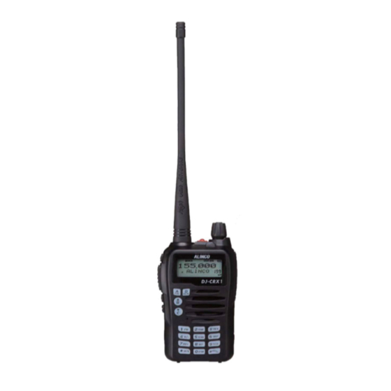
- Page 2 DJ-CRX1 Instruction Manual DJ-CRX1 Thank you for purchasing your new Alinco transceiver. Please read this manual carefully before using the product to ensure full performance, and keep this TONE manual for future reference as it contains information on after-sales service.
- Page 3 [MEMO]...
- Page 4 (which is higher than10 kA.). Note also that no car provides adequate protection of its passengers or drivers against lightning as well. Therefore, Alinco will not take responsibility for any danger associated with using its hand-held radios outdoor or inside the car during lightning.
- Page 5 Covering ranges ■ You may expect a range of approx.3km/2 miles or more at high-power when located on a flat, noise-free place like on a beach. However, it may vary drastically depending on how to wear and carry the radios, surrounding locations/conditions and static noise levels (below or near power transmission lines), etc.
- Page 6 Features ■ Output power selectable 5W/2W/1W ■ 200 PC-programmable channels ■ Li-Ion battery pack and stand-charger as standard accessories ■ Alphanumeric name tags ■ FM broadcast 76-108MHz receiver built-in ■ Selectable Battery-save parameters ■ Busy Channel Lockout ■ CTCSS/DCS Encode/Decode, DTMF ■...
- Page 7 WARNING To prevent any hazard during operation of Alinco’s radio product, in this manual and on the product you may find symbols shown below. Please read and understand the meanings of these symbols before starting to use the product. This symbol is intended to alert the user to an immediate danger that may Danger cause loss of life and property if the user disregards the warning.
- Page 8 Alert Environment and condition of use Use of this product may be prohibited or illegal outside of your country. Be informed in advance when you travel. It is recommended that you check local traffic regulations regarding the use of a radio equipment while driving.
- Page 9 The manufacturer declines any responsibilities against loss of life and property due to a failure of this product when used with or as a part of a device made by third parties. Use of third party accessory may result in damage to this product. It will void our warranty for repair. Handling this product Be sure to reduce the audio output level to minimum before using an earphone or a headset.
- Page 10 Securely plug the adapter into the wall outlet. Insecure installation may result in short-circuit, electronic shock and/or fire. Do not use the adapter if the plug or socket contacts are dirty. Overheating and/or short-circuiting may result in fire, electric shock and/or damage to the product. In case of emergency In case of the following situation(s), please turn off the product, switch off the source of power, then remove or unplug the power-cord.
- Page 11 Caution Environment and condition of use Do not use the product in proximity to a TV or a radio. It may cause interference or receive interference. Do not install in a humid, dusty or insufficiently ventilated place. It may result in electric shock, fire and/or malfunction.
- Page 12 The contents of this manual may be updated without any notice or obligation.Alinco cannot be liable for pictorial or typographical inaccuracies. Changes or modifications not expressly approved by the party responsible for compliance could...
-
Page 13: Table Of Contents
TABLE OF CONTENTS STANDARD ACCESSORIES/ADDITIONAL ACCESSORIES ................01 Standard Accessories ..................................01 BATTERY INFORMATION ................................. 02 Charging Operation ....................................02 Battery Charger Type ................................... 02 Notice for Charging Battery ................................02 How to Charge ......................................04 How to Store the Battery .................................. - Page 14 TABLE OF CONTENTS Receiving ........................................13 Transmitting ......................................13 Emergency Alarm ....................................14 Side Key [PF1]/[PF2] function instruction ..........................14 MONI Key Function ....................................15 Edit channel ......................................15 Delete channel ......................................15 VFO Frequency scanning limit ................................ 16 Turn On/Off FM Radio ..................................
- Page 15 TABLE OF CONTENTS Add or Cancel DTMF Sgnaling ............................... 28 Signaling Combination ..................................29 Frequency Step ...................................... 29 Wide/ Narrow FM Mode ..................................30 Frequency Reverse ....................................30 Talk Around ....................................... 31 Offset Frequency ....................................31 Editing Channel name ..................................32 Busy Channel Lockout ..................................
- Page 16 TABLE OF CONTENTS Self ID inquiry ......................................40 Tone Burst Frequency ..................................41 Battery Save ......................................41 FM radio ........................................42 PF1 and PF2 Key Function ................................43 Display Mode Setup ..................................... 44 Resume Factory Default ..................................44 AUXILIARY FUNCTIONS ...................................
-
Page 17: Standard Accessories/Additional Accessories
STANDARD ACCESSORIES/ADDITIONAL ACCESSORIES Take out the transceiver from the package carefully, check again and make sure the package without any accessories before you throw away. Contact the dealer immediately if any accessories lost or damaged. Standard Accessories Antenna Battery Charger AC Adaptor Li-ion Battery Belt Clip... -
Page 18: Battery Information
Battery Charger Type Please use our ALINCO's designated charger, other models may cause explosion. After installing the battery, when the radio displays low battery, please charge the battery. - Page 19 BATTERY INFORMATION Caution • Risk of explosion, generation of heat or leak of chemicals inside if the battery is replaced by an incorrect type or reverse polarity. Use always the recommended types of batteries in this manual only. • The battery pack isn't fully charged when shipped. It must be charged before use. •...
-
Page 20: How To Charge
BATTERY INFORMATION How to Charge 1.Plug the AC adaptor into the AC outlet(100V-240V), then plug the cable of AC adaptor into the DC jack, the indicator lights orange for 1 second and goes out---waits to charge. 2.Slide the battery or transceiver with battery into the charger; make sure the battery terminals are in contact with the charging terminals. -
Page 21: How To Store The Battery
BATTERY INFORMATION ▲ The charger is to charge the battery pack only. It is not an AC adapter to operate the radio. Never attempt to transmit the radio with using the charger as it will cause the damage to the charger and a repair/replace may become necessary. -
Page 22: Preparation
PREPARATION Installing / Removing the Battery ■ Installing the Battery Align the catches on the unit with the grooves on the battery pack, slide the pack forward and close the latch until it clicks. ■ Removing the Battery Pack Push the latch in the direction of the arrow, and pull out the battery pack. -
Page 23: Installing/Removing The Belt Clip
PREPARATION Installing / Removing the Belt Clip ■ Installing the Belt Clip: Place the belt clip to the grooves on the back of the transceiver, and then fix it by provided screws. ■ Removing the Belt Clip: Check the tightness of the fixing screws from time to time. (screws siz 2.5 x 5mm). -
Page 24: Getting Acquainted
GETTING ACQUAINTED LCD Display Frequency Reverse VOX Function Offset Direction Scan Skip DTMF Narrow band CTCSS Battery Capacity FUNC Icon Sub band receiving signal/Function Function Menu No. next menu Main Channel No. FM radio TX Power Busy Channel Lock NOTE: Battery capacity indicator(full) No power, replace battery pack or charge battery Battery capacity remnant... - Page 25 GETTING ACQUAINTED DJ-CRX1 TONE SCAN DTMF NOTE: Please do not close the microphone hole.
- Page 26 GETTING ACQUAINTED Antenna Lamp Power / Volume Switch Rotate it clockwise to turn on transceiver, rotate it anticlockwise until clicks to turn off the transceiver. When transceiver is power on, rotate it clockwise to increase volume, anticlockwise to reduce. TX/RX indicator, Main RX is Green, Sub RX is Blue, TX is Red LCD display Displays current frequency/channel and operations Speaker...
-
Page 27: Basic Operations
BASIC OPERATIONS Turn the Radio On & OFF Under power-off state, please turn [POWER]/[VOLUME] clockwise to turn on the transceiver. The transceiver will announces prompt tone and displays the current channel on screen. Under power-on state, please turn [POWER]/[VOLUME] anticlockwise till hearing "Click"... -
Page 28: Switch Between Channel Mode And Vfo Mode
BASIC OPERATIONS Switch between Channel mode and VFO mode Under standby state, press key to set main band as Channel mode or frequency mode(VFO). Channel Adjusting When transceiver in Channel mode or FM radio channel mode, rotate to adjust channel. to enter the downward channel, Press to enter the upward channel. -
Page 29: Fm Channel Searching
BASIC OPERATIONS 2. Enter the desired frequency by keypad. In VFO or FM VFO mode, you can directly input frequency by keypad. Example: To enter 145.0125, press [1][4][5][0][1][2] then 5 appears and sets automatically. To enter 435.100, press [1][4][5][1][0][0]. By pressing the last [0], a dot appears after the MHz unit and the frequency is set. -
Page 30: Emergency Alarm
BASIC OPERATIONS ensure it is not busy, press [PTT] key and talk to speaker. Please keep the distance between mouth and speaker to be 2.5-5CM, speak in normal tone to get the best acoustic fidelity. NOTE: When press and hold PTT key, transceiver is transmitting if the red LED light is on, release [PTT] key to receive calls. -
Page 31: Moni Key Function
BASIC OPERATIONS MONI Key Function Following functions may be assigned to the MONI key. Squelch off: Press [MONI] key, you can hear background noise. Press [MONI] again, squelch is mute. Monitor: Press [MONI] key, you can hear background noise. Release [MONI], squelch is mute. Turn the power on while holding the MONI key to enter to the set mode. -
Page 32: Vfo Frequency Scanning Limit
BASIC OPERATIONS VFO frequency scanning limit Setup the frequency of L1 channel, U1 channel, L2 channel and U2 channel will realize VFO frequency scanning border limited. When VFO frequency between L1 and U1 or L2 and U2, radio will scan between them. -
Page 33: Ctcss/Dcs Scan
BASIC OPERATIONS CTCSS/DCS Scan While in the CTCSS or DCS mode, Press key, the top left corner of LCD displays " " icon, press key to enter into CTCSS/DCS scan. Under this state, press change scan direction. When scan the matching CTCSS/DCS signaling, it will stay 5seconds and then go on scanning. -
Page 34: Frequency/Channel Scan
BASIC OPERATIONS Frequency/Channel Scan Under corresponding mode, press key, the top left corner of LCD displays " " icon, then press SCAN key to start frequency scan or channel scan. Frequency Scan Under VFO mode, frequency scan is available. This function is used for monitoring signal of various communication frequency by transceiver ‘step’... -
Page 35: Frequency Reverse
BASIC OPERATIONS Frequency Reverse Under standby state, press key, the top left corner of LCD displays " " icon, then press to set the current channel as frequency reverse, repeat above operation to turn off frequency reverse. "R" icon, it means current channel open the frequency reverse function, the TX When LCD displays frequency and RX frequency is interchanged, if CTCSS/DCS signaling is set, it will also interchange. -
Page 36: Keypad Lock
BASIC OPERATIONS When current group displays "EMPTY", press key, the top left corner of LCD displays " " icon, press and hold key until a beep sounds, and transceiver DTMF enters into DTMF edit state, LCD displays "___________", now you can enter desired DTMF data by keypad. -
Page 37: Function Menu Setup
FUNCTION MENU SETUP Menu 1-13 of this transceiver are channel operations. Channel operations temporarily changed the functions of current channel. When power off or channel has been changed, the relevant setup will be erased. Only under VFO mode, the channel operations will be saved until next change. Menu 14-31 is background operation, it is valid for all channels, the relevant setup will be saved until next change. - Page 38 FUNCTION MENU SETUP No CTCSS/DCS Decode CTCSS/DCS 51 groups fixed CTCSS decode+1 group self- R-CDC 62.5HZ-254.1Hz+Self defined Decode defined CTCSS decode. 000N-777I 1024 groups DCS decode No CTCSS/DCS encode/decode CTCSS/DCS 51 groups fixed CTCSS encode/decode + 1 group RT-CDC Encode/Decode 62.5HZ-254.1Hz+Self defined self-defined CTCSS encode/decode Synchronous...
- Page 39 FUNCTION MENU SETUP When current channel received matching RF Squelch mode signals, or matching optional signaling, or matching SIGNAL CT/TO setup CTCSS/DCS signaling, transceiver can hear the talking from the other party. Frequency step STEP 2.5K-50K 9 options in total size setup Wide / Narrow WIDE/NARROW...
- Page 40 FUNCTION MENU SETUP TX function is enabled in current channel TX OFF TX function is disabled in current channel FREQ Display sub band frequency or channel VOLT Display current battery voltage Sub band display DSPSUB setup Sub band display is disabled RADIO Display FM Radio frequency Keypad Voice...
- Page 41 FUNCTION MENU SETUP When scanning matched signal, transceiver will 5ST-15ST stop scanning for 5-15seconds then resume. Scan Dwell Time SCAN When scanning matched signal, transceiver will stop Setup scanning, 2seconds after signal disappeared, then resume. When finished function setting or enter into FUNCT function menu, icon disappeared.
- Page 42 FUNCTION MENU SETUP VOLT Displays current battery capacity. CALL Call function. Self define PF1/ ALARM Emergency alarm function. PF2 key function LAMP Lamp No function.
-
Page 43: Ctcss/Dcs Encode Setup
FUNCTION MENU SETUP CTCSS/DCS Encode Setup After pressing key, the top left corner of LCD displays " " icon then press key. Press key to choose menu 01 and display "T-CDC". Press enter into next menu, LCD displays " " icon, press select desired setting. -
Page 44: Ctcss/Dcs Encode / Decode Synchronous Setup
FUNCTION MENU SETUP NOTE: You may set the encoding and decoding tones separately. CTCSS/DCS Encode / Decode Synchronous Setup This function is for adjusting CTCSS/DCS encode/decode synchronous. After pressing key, the top left corner of LCD displays " " icon, then press key. -
Page 45: Signaling Combination
FUNCTION MENU SETUP Signaling Combination You may combine the signaling functions of different system. After pressing key, the top left corner of LCD displays " " icon,then press key. Press key to choose menu 05 and display "SIGNAL". Press key enter into next menu, LCD displays " "... -
Page 46: Wide/ Narrow Fm Mode
FUNCTION MENU SETUP Press key or key to confirm and exit. Available steps are 2.5K, 5K, 6.25K, 10K, 12.5K, 20K, 25K, 30K and 50KHz. This parameter is not available when the radio is in the Channel mode. Wide/ Narrow FM Mode After pressing key, the top left corner of LCD displays "... -
Page 47: Talk Around
FUNCTION MENU SETUP Press key or key to confirm and exit. This function is not available when Talk Around function is activated. Talk Around After pressing key, the top left corner of LCD displays " " icon, then press key. key to choose menu 09 and display "TAL KAR". -
Page 48: Editing Channel Name
FUNCTION MENU SETUP Editing Channel name After pressing key, the top left corner of LCD displays " " icon, then press key. Press key to choose menu 11 and display "NAME". Press enter into next menu, LCD displays " " icon, press to choose desired character, press key to confirm current character and move shift to next... -
Page 49: Prohibits Transmitting
FUNCTION MENU SETUP OFF: PTT operation is always possible without busy channel lockout. Press key or key to confirm and exit. Prohibits transmitting After pressing key, the top left corner of LCD displays" " icon, then press key. Press key to choose menu 13 and display "TX". Press key enter into next menu, LCD displays "... -
Page 50: Beep Sounds
FUNCTION MENU SETUP OFF: Sub band display is disabled. Press key or key to confirm and exit. Beep sounds After pressing key, the top left corner of LCD displays " " icon, then press key. Press key to choose menu 15 and display "BEEP". Press key enter into next menu, LCD displays "... -
Page 51: Voice Operated Transmission (Vox)/(An Optional Earphone-Microphone Is Necessary)
FUNCTION MENU SETUP OFF,10~270s of TOT for optional, each interval is 10 seconds. Press key or key to confirm and exit. Voice Operated Transmission (VOX)/(An optional earphone-microphone is necessary) When this function is on, the transmitting can be started by voice, no need to press [PTT] key. After pressing key, the top left corner of LCD displays "... -
Page 52: Automatic Power Off Time
FUNCTION MENU SETUP After pressing key, the top left corner of LCD displays " " icon, then press key. Press key to choose menu 18 and display "VDELAY". Press key enter into next menu, LCD displays " " icon, press select desired setting. -
Page 53: Squelch Level
FUNCTION MENU SETUP Press key to choose menu 20 and display "DTMF". Press key enter into next menu, LCD displays " " icon, press to select desired setting. 50MS: Each DTMF signal transmits 50ms, interval 50ms 100MS: Each DTMF signal transmits 100ms, interval 100ms 200MS: Each DTMF signal transmits 200ms, interval 200ms 300MS: Each DTMF signal transmits 300ms, interval 300ms 500MS: Each DTMF signal transmits 500ms, interval 500ms... -
Page 54: Scan Dwell Time
FUNCTION MENU SETUP Scan Dwell Time There are three kinds of scan dwell time for optional. After pressing key, the top left corner of LCD displays " " icon, then press key . Press key to choose menu 22 and display "SCAN". Press key enter into next menu, LCD displays "... -
Page 55: Lcd Backlight
FUNCTION MENU SETUP 1second then disappeared 2SEC: When finished function setting or enter into function menu, icon stay 2seconds then disappeared 3SEC: When finished function setting or enter into function menu, icon stay 3seconds then disappeared ALWAYS: Function icon is always display, only when pressing function key again, the icon will disappear. -
Page 56: Lcd Backlight Color
FUNCTION MENU SETUP LCD Backlight Color There are three kinds of backlight color for optional. After pressing key, the top left corner of LCD displays " " icon, then press key. Press key to choose menu 25 and display "COLOR". Press key enter into next menu, LCD displays "... -
Page 57: Tone Burst Frequency
FUNCTION MENU SETUP Tone Burst Frequency This function is used for waking up sleeping repeater, it needs a certain intensity of Tone Burst to wake up sleeping repeater. In general, as long as the repeater has been waked up, no need to transmit Tone Pulse again in preset time. -
Page 58: Fm Radio
FUNCTION MENU SETUP 1:2 The standby time between normal working state and battery saving mode is 1:2 1:3 The standby time between normal working state and battery saving mode is 1:3 1:5 The standby time between normal working state and battery saving mode is 1:5 1:8 The standby time between normal working state and battery saving mode is 1:8 AUTO: Battery save ratio is adjusting automatically. -
Page 59: Pf1 And Pf2 Key Function
FUNCTION MENU SETUP PF1 and PF2 Key Function After pressing key, the top left corner of LCD displays " " icon, then press key to enter function menu. key to choose menu 30 "PF1" or menu 31 "PF2". Press Press key enter into next menu, LCD displays "... -
Page 60: Display Mode Setup
FUNCTION MENU SETUP Display Mode Setup There are three kinds of display modes for optional. Press [MONI] key to turn on radio, hold [MONI] key until transceiver emits beep. Press key to choose No. 01 function item, it shows "DSP" on LCD. Press key enter into next menu, LCD displays "... - Page 61 FUNCTION MENU SETUP Press key to choose No. 02 function item, it shows "RESTOR" on LCD. Press key enter into next menu, LCD displays " " icon, press select desired setting. OFF: No operations. FACT: Resume all items to factory default, including channel and background settings.
-
Page 62: Auxiliary Functions
AUXILIARY FUNCTIONS For dealers only. Please contact the authorized importer of your area for more details. Cable Cloning With this function, you can copy the programming data of the transceiver to another one; it can copy parameters and memory programming data to another transceiver. Connection: use wire cloning cable of your own to connect main transceiver with sub-transceiver through reading / writing programmable interface. -
Page 63: Cable Cloning Instruction
AUXILIARY FUNCTIONS Cable cloning instruction Connect the cable to SP jack TONE TONE SCAN SCAN DTMF DTMF NOTE: Commonly available 3.5mm φ stereo miniplug audio cable is usable. -
Page 64: Optional Accessories
OPTIONAL ACCESSORIES EA-211 VHF & FM radio Antenna EBC-41 Belt Clip EBP-92 Li-ion Battery Pack (DC 7.4V 1800mAh) EDC-202 Li-ion Battery Charger EDC-190E AC Adaptor (220V Linear type) EDC-191E AC Adaptor (220V) EDC-191T AC Adaptor (120V) EME-56A Earphone Microphone EMS-76 Speaker microphone... -
Page 65: Recommended Installation Of Earphone Microphone
RECOMMENDED INSTALLATION OF EARPHONE MICROPHONE Earphone Use a clip to fix with collar. Clip the PTT unit closer to your mouth. Carry the radio on the side or the back of your body, and the cable should go around the back as shown. Clamp the excessive length of cable at your waist... -
Page 66: Technical Specification
TECHNICAL SPECIFICATION General Receiving Part Frequency Range VHF: 136~174MHz Wide band narrow band Channel Capacity 200 channels Sensitivity ≤0.25μV ≤0.35μV 25KHz (wide band) (12dB SInAD) Channel Spacing 12.5KHz (narrow band) Adjacent Channel ≥65dB ≥60dB Phase-locked Selectivity 0.1KHz Step Intermodulation ≥60dB ≥60dB Operation Voltage 7.4V DC ±20% Spurious Rejection... -
Page 67: Trouble Shooting Guide
TROUBLE SHOOTING GUIDE Problem Corrective Action A.The battery may be exhausting. Recharge or replace the battery. No power B.The battery may not be installed correctly. Remove the battery and install it again. Battery power dies shortly after The battery life is finished. Replace the battery pack with a new one. charging. -
Page 68: Attached Chart
ATTACHED CHART CTCSS Frequency Chart 62.5 94.8 136.5 177.3 218.1 67.0 97.4 141.3 179.9 225.7 69.3 100.0 146.2 183.5 229.1 71.9 103.5 151.4 186.2 233.6 74.4 107.2 156.7 189.9 241.8 77.0 110.9 159.8 192.8 250.3 79.7 114.8 162.2 196.6 254.1 82.5 118.8 165.5... -
Page 69: 1024 Groups Dcs Frequency Chart
ATTACHED CHART 1024 groups DCS frequency chart... - Page 70 ATTACHED CHART...
- Page 71 ATTACHED CHART...
- Page 72 [MEMO]...
Need help?
Do you have a question about the DJ-CRX1 and is the answer not in the manual?
Questions and answers