Table of Contents
Advertisement
Quick Links
Advertisement
Table of Contents

Subscribe to Our Youtube Channel
Related Manuals for Alinco DJ-G46T


Summary of Contents for Alinco DJ-G46T
- Page 1 Alinco Incorporated, Electronics Division Yodoyabashi Dai-bldg 13F 4-4-9 Koraibashi, Chuo-ku, Osaka 541-0043 Japan Phone: +81-6-7636-2362 Fax: +81-6-6208-3802 http://www.alinco.com E-mail:export@alinco.co.jp Copyright Alinco, lnc. PS1096/FNFG-FI Printed in China...
- Page 2 UHF FM TRANSCEIVER DJ-G46T Instruction Manual Thank you for purchashing your new Alinco transceiver.Please read this manual carefully before using the product to ensure full performance, and keep this manual for future reference as it contains information on after-sales service.
- Page 3 [MEMO]...
- Page 4 Introduction Thank you very much for purchasing this excellent Alinco transceiver. Our products are ranked among the finest in the world. This radio has been manufactured with state of the art technology and it has been tested carefully at our factory. It is designed to operate to your satisfaction for many years under normal use.
- Page 5 Alinco accessories and the radio has not been disassembled by the customer. The factory has tested and made the equipment compatible to IP54 certification during engineering.
- Page 6 • Connect the eguipment into an outlet on a circuit different from that to which the receiver is connected. • Consult the dealer or an experienced radio/TVtechnician for help. CAUTION: Changes or modifications to this device,note expressly approved by Alinco,Inc.could void your authority to operate this device under.
- Page 8 Your ALINCO DJG46 operates on GMRS frequencies GENERAL MOBILE RADIO SERVICE(GMRS) GMRS is a two-way personal radio service available to an individual (one man or one woman) to facilitate the activities of the individual's immediate family members. GMRS is not authorized for business uses.
- Page 9 Features ■ Li-Ion battery pack and stand-charger as standard accessories ■ FM broadcasting 76.1-107.9MHz receiver built-in ■ Sub-tone (CTCSS/DCS) Encode/ Decode and DTMF/ANI Tested to comply MIL-STD-810G -Shock: Method 514.6/I,IV -Vibration: Method 516.6/I...
- Page 10 Alert Environment and condition of use Use of this product may be prohibited or illegal outside of your country. Be informed in advance when you travel. It is recommended that you check local traffic regulations regarding the use of a radio equipment while driving.
- Page 11 The manufacturer declines any responsibilities against loss of life and property due to a failure of this product when used with or as a part of a device made by third parties. Use of third party accessory may result in damage to this product. It will void our warranty for repair. Handling this product Be sure to reduce the audio output level to minimum before using an earphone or a headset.
- Page 12 Securely plug the adapter into the wall outlet. Insecure installation may result in short-circuit, electronic shock and/or fire. Do not use the adapter if the plug or socket contacts are dirty. Overheating and/or short-circuiting may result in fire, electric shock and/or damage to the product. In case of emergency In case of the following situation(s), please turn off the product, switch off the source of power, then remove or unplug the power-cord.
- Page 13 Alert Environment and condition of use Do not use the product in proximity to a TV or a radio. It may cause interference or receive interference. Do not install in a humid, dusty or insufficiently ventilated place. It may result in electric shock, fire and/or malfunction.
- Page 14 Use a clean, dry cloth to wipe off dirt and condensation from the surface of the product. Never use thinner or benzene for cleaning. Check with your local waste officials for details on recycling or proper disposal of the electronics product, battery-packs and accessories in your area.
-
Page 15: Table Of Contents
CONTENTS STANDARD ACCESSORIES/OPTIONAL ACCESSORIES ............. 1 Standard Accessories .........................1 BATTERY INFORMATION ........................ 2 Charging Operation ..........................2 Battery Charger Type ..............................2 Notice For Charging Battery ............................2 How To Charge The Battery Pack ..........................5 How To Store The Battery ............................6 INSTALLATION & CONNECTION ....................7 Installing / Removing The Li-Ion Battery ........................7 Installing / Removing The Belt Clip ..........................7 Accessories ................................8... - Page 16 CONTENTS Side Key[PF2](Keypad lock) ............................14 Squelch Off ................................14 Receiving ...................................15 Transmitting ................................15 Resetting ...................................15 KEY ASSIGNMENT........................... 16 ADVANCED OPERATIONS......................18 Call ....................................18 Emergency ................................18 Monitor ..................................18 Adiustment Squelch Level ............................18 Reverse ..................................18 Talk Around ................................19 Key Lock ..................................19 Tx Power Switch ................................19 Instantaneously Squelch Off ............................19 VOX Sensitivity Level ..............................20...
- Page 17 CONTENTS Lighting ..................................21 Backlight Settiing ...............................21 Language Setting ..............................21 Color Setting ................................21 P1 KEY OPERATIONS........................22 Tone Squelch/DCS Squelch (Sub tone CTCSS/DCS) Encode/Decode Tones Synchronized Setup ......22 Scan ..................................22 P2 KEY OPERATIONS........................23 Turn On/ Off FM Radio Receiver ..........................23 Squelch Level ................................23 Tone Burst .................................23 OPTIONAL ACCESSORIES..................
-
Page 18: Standard Accessories/Optional Accessories
STANDARD ACCESSORIES/OPTIONAL ACCESSORIES Standard Accessories Belt Clip Battery Charger Battery AC Adaptor Antenna Instruction Hand Strap Manual NOTE: Accessories may differ depending on the version you have purchased. Please contact your local dealer for details of standard accessories and the warranty-policy before purchase. Professional FM Transceiver... -
Page 19: Battery Information
Battery Charger Type Please use Alinco's designated charger, other models may cause explosion and injury. After installing the battery, when the radio displays low battery, please charge the battery. - Page 20 BATTERY INFORMATION Caution • Risk of explosion, generation of heat or leak of chemicals inside if the battery is replaced by an incorrect type or reverse polarity. Use always the recommended types of batteries in this manual only. • The battery pack isn't fully charged when shipped. It must be charged before use. •...
- Page 21 BATTERY INFORMATION IMPORTANT ■ Handling and storing information of batteries and battery packs. Batteries contain flammable materials. Mishandling shall cause batteries to rupture producing extreme heat, fire, deteriorate or cause damages to you and your properties. Please care about the following information.
-
Page 22: How To Charge The Battery Pack
BATTERY INFORMATION How to Charge the Battery Pack 1.Plug the AC adaptor into the AC outlet(100V-240V), then plug the cable of AC adaptor into the DC jack, the indicator lights RED on for 1 second then turns to GREEN on---waits to charge. -
Page 23: How To Store The Battery
BATTERY INFORMATION NOTE: ▲ Trouble means battery heating, short-circuit or charger malfunction. Remove the battery pack from the charger immediately and contact to your local dealer for services. ▲ The max trickle pre-charging time is 30 minutes. In case the red indicator continues to blink longer, please stop charging and consult with your local dealer for services. -
Page 24: Installation & Connection
INSTALLATION & CONNECTION Installing / Removing the Li-ion Battery 1.Match the three grooves of the battery pack with the corresponding guides on the back of the transceiver, then push it. 2.Press the battery and transceiver firmly together until the release latch on the top of the transceiver locks. After hearing a“click”sounds, the battery has been locked. -
Page 25: Accessories
INSTALLATION & CONNECTION Accessories Open the jack cover and insert the accessory plug into the jack,as shown. When the accessory is not used, please be sure to close the cover securely. NOTE: 1. If you wear the earphones or earphone/microphone in a place where static electricity tends to accumulate or in your clothes, you may feel a static shock in your ears. -
Page 26: Installing The Hand Strap
INSTALLATION & CONNECTION Installing the Hand Strap Attach the hand strap as shown. Professional FM Transceiver... -
Page 27: Getting Acquainted
GETTING ACQUAINTED LCD Display Following are the meaning of the icons and signs shown on the display. Some icons may not appear while operating this product due to pre-programming status by your dealer. Offset Direction Reverse Priority Scan Talk Around Narrow CTCSS Battery Capacity... -
Page 28: Front Panel
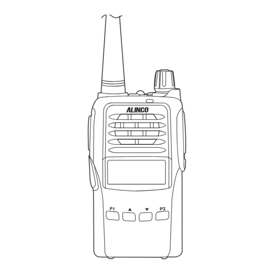
GETTING ACQUAINTED Front Panel Emergency Alarm Antenna Jacklight Power/volume switch LED indicator, green light when receiving , red light when transmitting Speaker Microphone ※Do not close the microphone hole. DJ-G46 Up/Down adjusting key P2 key P1 key Short press: FM radio Short press: Tone/DCS squelch Long press: Squelch Level GMRS TRANSCEIVER... -
Page 29: Side Panel
GETTING ACQUAINTED Side Panel PTT key Accessory and PC programming port PF1 key PF2 key Belt Clip Battery Left Panel Right Panel Professional FM Transceiver... -
Page 30: Basic Operations
BASIC OPERATIONS Power On and off Turn 【 POWER 】 / 【 VOLUME 】 dial clockwise to power on. Turn it counterclockwise to power off. Adjusting Audio output Level Press PF2 key to monitor white noise to refer to the current audio level. Turn 【... -
Page 31: Emergency Alarm Function
BASIC OPERATIONS Emergency Alarm Function While Stand-by state, press this key for 3 seconds to enable the emergency alarm function. When activated the function, the radio will sound an alarm beep and start transmitting the alarm beep. Adjusting Channel Press key/ key to choose the desired channel. -
Page 32: Receiving
BASIC OPERATIONS Receiving Select the channel that you wish to operate. When a signal is received on the channel that you selected, and S-meter is displayed on the LCD, then the received signal can be heard. The RX indicator also lights green at this time. NOTE: Please be aware of the squelch level and selective-calling settings such as CTCSS and DCS as you may risk not hearing the receiving signal. -
Page 33: Key Assignment
KEY ASSIGNMENT NAME FUNCTION CALL LCD displays DTMF data and group number (total 16 groups)of current group. Emergency Emergency alarm function. Under the standby conditions. pressing and releasing the programmed key. it beeps and enters Monitor the monitor state. While in Monitoritignores CTCSS/DCS decode and enables monitoring all incoming signals. - Page 34 KEY ASSIGNMENT NAME FUNCTION VOX Sensitivity When this function is on. the transmitting can be started by voice, no need to press [PTT] key. Level If transceiver returns to receive mode instantly after VOX calling, it may cause calling voice VOX Delay time missing.
-
Page 35: Advanced Operations
ADVANCED OPERATIONS Call Under the standby conditions, press the programmed key to transmit the prestored and selected DTMF signaling. ※Set DTMF CALL Signal to use Call function. Emergency Under the standby conditions press the proqrammed key to transmit the prestored and selected DTMF signaling. -
Page 36: Talk Around
ADVANCED OPERATIONS Talk Around Under the standby conditions, pressing the programmed key, it beeps and activates TalkAround. In case of semi-duplex channels, it will transmit on receiving frecuency and CTCSS/DCS encode/ decode setting will be reversed. This ables the user to talk to other users without using the repeater. Press the key again, it beeps twice and Talk-around is deactivated. -
Page 37: Vox Sensitivity Level
ADVANCED OPERATIONS VOX Sensitivity Level Under the standby conditions, pressing the programmed key, it beeps and enters the VOX sensitivity level select state. VOX Delay Time Under the standby conditions, pressing the programmed key, it beeps and enters the vox delay time select state. -
Page 38: Scan Add And Del
ADVANCED OPERATIONS Scan Add and Del Under the standby conditions, pressing the programmed key, it can select to add or delete from scan group. Lighting Under the standby conditions, pressing the programmed key, it lits jacklight. Backlight Settiing Under the standby conditions, pressing the programmed key, it beeps and enters the backlight setting state. -
Page 39: P1 Key Operations
P1 KEY OPERATIONS Tone Squelch / DCS Squelch (Sub tone CTCSS / DCS) Encode/Decode Tones Synchronized Setup Short press 【 P1 】 key to choose the desired CTCSS / DCS encode tone. Available CTCSS tones: 67Hz- 254.1Hz, 50 tones in total, Deafault is OFF. DCS: 017N-765I, 232 codes, "N"... -
Page 40: P2 Key Operations
P2 KEY OPERATIONS Turn On/ Off FM Radio Receiver Short pressing 【 P2 】 key, FM Radio is enabled. LCD displays 'FM' and starts receiving FM broadcasting frequency. Repeat the operations to turn off. While listening to the FM broadcasting, press key or key to start scanning. -
Page 41: Optional Accessories
OPTIONAL ACCESSORIES EBC-34 Belt Clip EBP-87 Li-ion Battery Pack (DC 7.4V 1500mAh) EBP-88 Li-ion Battery Pack (DC 7.4V 1700mAh) EDC-189 Li-ion Battery Charger EDC-191T AC Adapter (AC120V) EME-56A Earphone Microphone EMS-76 Speaker microphone Professional FM Transceiver... -
Page 42: Recommended Installation Of Earphone Microphone
Recommended Installation Of Earphone Microphone Earphone Use a clip to fix with collar. Clip the PTT unit closer to your mouth. Carry the radio on the side or the back of your body, and the cable should go around the back as shown. Clamp the excessive length of cable at your waist. -
Page 43: Auxiliary Functionsstarting Takes
AUXILIARY FUNCTIONSSTARTING TAKES Key Programming The 【 PF1 】 , 【 PF2 】 , 【 P1 】 and 【 P2 】 keys are programmable. NOTE: The keys can be programmed of long press and short press, if program of short press, the function will be activated when press the programmed key, if program of long press, the function will be activated when press and hold the key for programmed time. -
Page 44: Default Setting
DEFAULT SETTING Memory Channel GMR Channels FM Radio PF1 long press key Light Switch Key Beep PF1 short press key SCAN Offset Frequency Selup PF2 short press key MONI Channel Scan Skip PF2 long press key KEY LOCK TX Power Selection High Voice Prompting Reverse / Talk Around... -
Page 45: Technical Specifications
TECHNICAL SPECIFICATIONS Audio Response General +1~-3dB(0.3~2.55KHz) Hum & Noise ≥45dB Frequency Range 462.5500-462.7250, 462.5625-462.7125MHz 467.5500-467.7250, 467.5625-467.7125MHz Audio Distortion ≤5% Channel Capacity 128 channels Audio Power 1000mW/10% Operating Voltage 7.4V DC ±20% Output More than 14 Hours (1800mAh), by Battery Life 5-5-90 work cycle Transmitting Part Frequency Stability ±2.5ppm... -
Page 46: Trouble Shooting Guide
TROUBLE SHOOTING GUIDE Problem Corrective Action A.The battery may be exhausting. Recharge or replace the battery. B.The battery may not be installed correctly. Remove the battery No power and install it again. C.The power switch is broken; send it to local dealers to repair. D.Battery life is end;... - Page 47 C.Earphone jack is broken, please contact with local dealers to repair. NOTE: Alinco guarantees the supply of minimum-necessary spare parts such as battery-packs, components and mechanical parts for at least 5 years after the production of this product is terminated except in case of accidents beyond control.
-
Page 48: Attached Chart
ATTACHED CHART Channel Frequency Chart Channel Channel NO. RX Frequency TX Frequency NO. RX Frequency TX Frequency Name Name 462.56250 462.56250 CH 001 462.60000 462.60000 CH 017 462.58750 462.58750 CH 002 462.62500 462.62500 CH 018 462.61250 462.61250 CH 003 462.65000 462.65000 CH 019 462.63750... -
Page 49: Ctcss Frequency Chart
ATTACHED CHART CTCSS Frequency Chart 67.0 94.8 131.8 171.3 203.5 69.3 97.4 136.5 173.8 206.5 71.9 100.0 141.3 177.3 210.7 74.4 103.5 146.2 179.9 218.1 77.0 107.2 151.4 183.5 225.7 79.7 110.9 156.7 186.2 229.1 82.5 114.8 159.8 189.9 233.6 85.4 118.8 162.2... -
Page 50: 1024 Groups Dcs Frequency Chart
ATTACHED CHART 1024 groups DCS Frequency Chart Professional FM Transceiver... - Page 51 ATTACHED CHART Professional FM Transceiver...
- Page 52 ATTACHED CHART Professional FM Transceiver...
- Page 53 [MEMO]...
Need help?
Do you have a question about the DJ-G46T and is the answer not in the manual?
Questions and answers