
Related Manuals for JGR TLS


Summary of Contents for JGR TLS
- Page 1 TLS Tunable Laser Source User Manual All information contained herein is believed to be accurate and is subject to change without notice. No responsibility is assumed for its use. JGR Optics Inc, 2015.
-
Page 3: Table Of Contents
TLS User Manual TABLE OF CONTENTS COMPLIANCE ......................1 FDA-CDRH C OMPLIANCE .....................1 CSA / IEC C OMPLIANCE ......................1 OMPLIANCE .........................1 GENERAL INFORMATION ..................2 TLS T UNABLE ASER OURCE VERVIEW ................2 UTPUT ........................3 EATURES ........................3 PPLICATIONS ........................3 CCESSORIES ........................3 SAFETY INFORMATION ..................4... - Page 4 TLS User Manual Cleaning the Unit ....................18 Cleaning the Connector Ends ................18 Cleaning Jumper Connectors ................19 ROUBLESHOOTING ......................20 Connector Issues ....................20 Other potential Issues ..................20 STORAGE AND SHIPPING ................... 22 JGR O ETURNING NSTRUMENTS TO PTICS .................
-
Page 5: Compliance
TLS User Manual COMPLIANCE FDA-CDRH Compliance Under the US Food and Drug Administration (FDA) Center for Devices and Radiological Health (CDRH), the unit complies with the Code of Federal Regulations (CFR), Title 21, Subchapter J, which pertains to laser safety and labeling. -
Page 6: General Information
TLS is over 100nm/s allowing users to access their desired wavelength quickly and efficiently. The TLS offers a user friendly LED display that can be controlled manually with the use of the front panel buttons, but also offers the possibility of remote control through GPIB and RS232. -
Page 7: Output Port
TLS User Manual Output Port The output port of the TLS tunable laser source is equipped with an ultra-low backreflection APC connector. Extreme care must be taken to avoid damaging the connector when plugging and unplugging output jumper. Connection must be kept clean and should be inspected before every mating. -
Page 8: Safety Information
Failure to comply with any of these instructions or with any precaution or warning contained in the User Manual is in direct violation of the standards of design, manufacturing, and intended use of the unit. JGR Optics assumes no liability for the customer’s failure to comply with any of these safety requirements. -
Page 9: Classification
Class 1 instrument. Laser Specifications The laser contained in the TLS source is Class 1 laser as specified under the laser classification of the US Food and Drug Administration (FDA) Center for Devices and Radiological Health (CDRH). Laser specifications are provided in Table 2 below. -
Page 10: Electrical Shock Hazards
If the equipment is used in a manner not specified by the manufacturer, the protection provided by the equipment may be impaired. Only technicians authorized by JGR Optics should carry out the repairs. In addition to voiding the warranty, opening the unit (even when unplugged) can expose you to potential shock hazards. -
Page 11: Getting Started
“SAFETY INFORMATION” section on page 4. This manual contains complete operating instructions for safe and effective operation of the TLS Tunable Laser Source. It is recommended that users of the TLS familiarize themselves with contents of this manual before using the instrument. -
Page 12: Operational Requirements
Ensure the unit is operational: Connect the unit to a power source using the provided power cord Set the power switch to ON to initialize the TLS Tunable Laser Source, and observe the power-up sequence: Model number and firmware version of the meter are displayed ... -
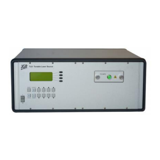
Page 13: Product Overview
Product Overview Front Panel and Key Description A front view of the TLS Tunable Laser Source is shown on Figure 2 and a detailed description of keys and LEDs is provided in Table 5 on next page. TLS Tunable Laser Source... - Page 14 Power Input (also contains the user-replaceable fuse) TRIG IN BNC connector used to receive a TTL trigger signal from an external device to make the TLS Tunable laser source to move one (1) wavelength step. TRIG OUT BNC connector used to send a TTL trigger function to an external devide to indicate that the TLS tunable laser source has stabilized on the required wavelength.
-
Page 15: Operation
TLS User Manual OPERATION Before using the TLS Laser Source, make sure to allow a warm-up time of at least 30 minutes for laser stabilization. Powering Up the Tunable Laser Source To power up the laser source: 1. Connect the meter to an AC power source using the power cord provided. -
Page 16: Sweep Mode
TLS User Manual For example, to change the TLS laser source wavelength from 1308.0 nm to 1550.1 nm, follow these steps: Press the 100 up key twice to go from 1308.xx to 1508.xx Press the 10 up key five times to go from 1508.xx to 1558.xx ... -
Page 17: User Menu Operation
TLS Tunable Laser Source with an external device like a power meter. The Trigger In function can be enabled by pressing the TRGIN softkey in the menu. When enabled, the TLS will advance one (1) wavelength step. -
Page 18: Messages And Symbols
TLS User Manual Messages and Symbols The messages/symbols displayed by the TLS Tunable Laser Source are shown in Table 7. Table 7: TLS Tunable Laser Source Display Messages and Symbols Display Description TLS VER X.XX Displayed momentarily during the power-up sequence... -
Page 19: Calibration Period
TLS User Manual Calibration Period JGR Optics recommends a 1 year calibration period for the TLS Tunable Laser Source. TLS-UM-00001 Rev 001... -
Page 20: Programming Guide
In order to establish a serial communication between a computer and the TLS, the computer’s COM port must be configured as described in Table 8. To connect the TLS to the computer, a standard 9 pins straight RS-232 cable is required. Only three pins, Txd, Rxd and GND are needed. -
Page 21: Programming Over Usb
TLS User Manual Programming Over USB It is also possible to remote control the TLS Tunable Laser Source via USB by using a USB to DB9 adapter cable. The same RS-232 commands are used for USB communication. Table 8: Serial Communication Settings Transmission Rate Selectable in the “User Menu”. -
Page 22: Maintenance And Troubleshooting
TLS User Manual MAINTENANCE AND TROUBLESHOOTING Maintenance Warning Devices with malfunctioning lasers must be returned to the manufacturer for repair. Cleaning the Unit 1. Unplug the unit from the line power. 2. Clean the enclosure with a damp cloth. 3. Do not plug the unit back until it is completely dry. -
Page 23: Cleaning Jumper Connectors
8. Reinstall the connector onto the panel. 9. Reinstall the connector panel. To avoid damaging the input and output port fibers, make one or two large loops in the fibers when reinstalling the panel. TLS Tunable Laser Source FC A / PC MENU ENABLE... -
Page 24: Troubleshooting
If cleaning is not sufficient, the FC/APC connector can be polished. Other potential Issues There are very few things that can go wrong with the TLS Tunable Source that could be solved by the user. Refer to Table 9 on next page for a list of potential problems and solutions. - Page 25 Source to a reliable power source, and wait a few minutes. Turn the unit ON. SYSTEM ERROR Internal Try to restart the TLS Tunable communications error Laser Source; if the problem remains, contact JGR Optics. END LIMIT Source motor overrun...
-
Page 26: Storage And Shipping
As indicated above, please ship the returned material in the original shipping box and packing material. If these are not available, follow the guidelines below: 1. Contact JGR Optics to obtain a RMA number; 2. Cover the front panel with foam to prevent damage;... -
Page 27: Contact Information
TLS User Manual Contact Information JGR Optics Inc. Phone: 613-599-1000 160 Michael Cowpland Drive Fax: 613-599-1099 Ottawa, Ontario, Canada sales@jgroptics.com K2M 1P6 www.jgroptics.com TLS-UM-00001 Rev 001... -
Page 28: Specifications
TLS User Manual SPECIFICATIONS Specifications are provided here as a reference only and may be changed without notice. Please refer to JGR Optics’s website for the most recent specifications. TLS-UM-00001 Rev 001... -
Page 29: Remote Control Commands
TLS User Manual REMOTE CONTROL COMMANDS Command Syntax and Style Program Message Formats A program message consists of a command header, followed by its required parameters. The parameters must be separated from the command header by a space, for example, *ESE 10. Multiple parameters must be separated by a comma ( , ). -
Page 30: Specifying The Command Path
TLS User Manual Specifying the Command Path In order to use a command in the command tree, the meter must know the full path to the command. If the command is the first command in the program message, the command header must contain the full path to the command. -
Page 31: Implemented Status Structures
TLS User Manual Implemented Status Structures TLS Tunable Laser Source has the following status data structures implemented: IEEE 488.2 defined standard registers (standard status structure) The 488.2 standard status structure consists of four registers: status byte register ... - Page 32 TLS User Manual Bit 6, as the service request bit, is set to 1 if a service request has been generated. Bit 6, as the master summary bit, is set when there is at least one reason for the laser source to request service from the controller. That is, the master summary bit is set if any summary bit in the status byte register is set and if the corresponding bit in the service request enable register is also set.
-
Page 33: Queues
Queues Input Queue The input queue in the TLS Tunable Laser Source is a first-in-first-out (FIFO) queue and is 128 characters in length. Data bytes received from the controller are placed in the input queue in the order received. When a full message is received, it is transferred to the parser. -
Page 34: Output Queue
However, the RS232C interface has no DAQ signal and cannot be signaled when the input queue becomes full. Therefore, characters sent to the TLS Source are lost. If a new program message is received before the response to a query in a previous message is read, the output queue is cleared, MAV is set to false, and the query error bit is set. - Page 35 TLS User Manual -130 Suffix error An error was detected in the suffix sent with the command, but the parser cannot be more specific. -220 Parameter error An error was detected in a parameter, but the control block cannot be more specific.
-
Page 36: Ieee 488.2 Common Commands And The Scpi Command Tree
TLS User Manual IEEE 488.2 Common Commands and the SCPI Command Tree IEEE 488.2 Common Commands Command Parameter Response Minimum Maximum *CLS *ESE Integer *ESE? Integer *ESR? Integer *IDN? String *OPC *OPC? Integer *RST *SRE Integer *SRE? Integer *STB? Integer... -
Page 37: Scpi Command Tree
TLS User Manual SCPI Command Tree All commands other than the IEEE 488.2 common commands are listed in the following table. Command Parameters Response [:SOURce] :ENABle Boolean :ENABle? Boolean :WAVelength Num Val| MIN|MAX :WAVelength? None|MIN|MAX Num Val :SWEEP :START :WAV... - Page 38 TLS User Manual :PTRansition? Num Val :QUEStionable [:EVENt]? Num Val :CONDition? Num Val :ENABle Num Val :ENABle? Num Val :NTRansition Num Val :NTRansition? Num Val :PTRansition Num Val :PTRansition? Num Val :PRESet :SYSTem :ERRor[:NEXT]? Num Val, String :VERSion? String :CAPability?
-
Page 39: Description Of Individual Commands
TLS User Manual Description of Individual Commands IEEE-488.2 Common Commands Clear Status Command Syntax *CLS Function Clears the following queues and registers: Error queue Standard event status register Status byte register Operation event register Questionable event register... - Page 40 Function The *IDN query returns a string value which identifies the manufacturer, instrument type and firmware version. Example *IDN? Returns "JGR Optics Inc., BR5, XXXXXXX, Y.YY" Where: <XXXXXXX> = device serial number <Y.YY> = firmware revision number Operation Complete Command...
- Page 41 TLS User Manual Operation Complete Query Syntax *OPC? Function Places a “1” in the output queue of the source when all pending operations have been completed. Because the “1” is not always placed in the output queue immediately, the status byte register should be polled and the MAV bit checked to determine if there is a message available in the output queue.
- Page 42 TLS User Manual Read Status Byte Query Syntax *STB? Function Returns the contents of the status byte register as an integer that, when converted to a binary number, represents the bit values of the register. The bit value for bit 6 of the register is the MSS bit value, not the RQS bit value.
-
Page 43: Scpi Commands
TLS User Manual SCPI Commands [:SOURce]:ENABle Syntax [:SOURce]:ENABle<space>[0|1] OR [OFF|ON] Function This command sets the state of the laser. False or OFF: Turns OFF the laser True or ON: Turns ON the laser Example ENAB ON turns ON the laser. - Page 44 TLS User Manual [:SOURce]:WAVelength? Syntax [:SOURce]:WAVelength?<space>[MIN|MAX] Function Returns the current or specified output source wavelength in nm No parameter: returns the current wavelength MIN or MAX: returns the first or last wavelength respectively. Example WAV? MIN returns: 1310.
- Page 45 TLS User Manual [:SOURce]:SWEEP:START:WAV? Syntax [:SOURce]:SWEEP:START:WAV? Function Returns the current start wavelength of the sweep mode. Example SWEEP:START:WAV? Returns 1260 for example which could be the minimum wavelength of the laser, 1260 nm. [:SOURce]:SWEEP:STOP Syntax [:SOURce]:SWEEP:STOP Function Stops the wavelength sweep...
- Page 46 TLS User Manual [:SOURce]:SWEEP:STEP Syntax [:SOURce]:SWEEP:STEP<space>[step] Function Sets the sweep wavelength step of the sweep mode in nm Example SWEEP:STEP 10 Sets the wavelength step of the sweep mode to 10 [:SOURce]:SWEEP:STEP? Syntax [:SOURce]:SWEEP:STEP? Function Returns the current or specified sweep wavelength step of the...
- Page 47 TLS User Manual [:SOURce]:SWEEP:TRIGIN Syntax [:SOURce]:SWEEP:TRIGIN Function This command is used to enable the TRIG IN mode. Refer to the Sweep mode section in the manual for more information. False or OFF: Disables the TRIG IN mode True or ON: Enables the TRIG IN mode...
- Page 48 TLS User Manual :STATus:OPERation[:EVENt]? Syntax :STATus:OPERation[:EVENt]? This command reads the value of the Operation Status Event Function Register. Only Bit 1 is used in TLS. Example :STATus:OPERation[:EVENt]? returns 2 if an event was detected :STATus:OPERation:CONDition? Syntax :STATus:OPERation:CONDition? This command reads the value of the Operation Status Condition Function Register.
- Page 49 TLS User Manual :STATus:OPERation:NTRansition Syntax :STATus:OPERation:NTRansition This command determines which bits in the Status Operation Function Condition Register will set the corresponding bit in the Standard Operation Event Register when that bit has a negative transition Example :STATus:OPERation:NTRansition 2 sets bit 1 as the corresponding...
- Page 50 TLS User Manual :STATus:QUEStionable[:EVENt]? Syntax :STATus:QUEStionable[:EVENt]? Returns the decimal sum of the bits in the Data Questionable Function Event Register. Example :STATus:QUEStionable[:EVENt]? Returns 2 if only bit 1 is set to 1 :STATus:QUEStionable:CONDition? Syntax :STATus:QUEStionable:CONDition? Returns the decimal sum of the bits in the Data Questionable Function Condition Register.
- Page 51 TLS User Manual :STATus:QUEStionable:NTRansition Syntax :STATus:QUEStionable:NTRansition This command determines which bits in the Data Questionable Function Condition Register will set the corresponding bit in the Data Questionable Event Register when that bit has a negative transition (1 to 0). Example...
- Page 52 TLS User Manual :STATus:PRESet Syntax :STATus:PRESet This command initializes all the status registers: Function OPERation_ENABle = 0x7fff (32767); QUEStionable_ENABle = 0x7fff (32767); OPERation_PTRansition = 0x7fff (32767); QUEStionable_PTRansition = 0x7fff (32767); OPERation_NTRansition = 0; QUEStionable_NTRansition = 0; Example :STATus:PRESet :SYSTem:ERRor? Syntax...
- Page 53 TLS User Manual :SYSTem:COMMunicate:GPIB[:SELF]:ADDRess Syntax :SYSTem:COMMunicate:GPIB[:SELF]:ADDRess<space><numeric_val ue> Function Sets the GPIB address. The factory-set GPIB address is 21. When the address is changed, the interface immediately responds to the new address. Example :SYST:COMM:GPIB:ADDR 7 :SYSTem:COMMunicate:GPIB[:SELF]:ADDRess? Syntax :SYSTem:COMMunicate:GPIB[:SELF]:ADDRess? Function Returns the GPIB address.
- Page 54 TLS User Manual :INITiate[IMMediate][:ALL] :INITiate[IMMediate][:ALL] Syntax Function Initiates the Trigger mode, when the sweep sequence is completed after in trig signal, the Trigger mode goes back to idle Example :INITiate[IMMediate][:ALL] TLS-UM-00001 Rev 001...
Need help?
Do you have a question about the TLS and is the answer not in the manual?
Questions and answers