Table of Contents
Advertisement
Advertisement
Table of Contents

Related Manuals for JGR RL1


Summary of Contents for JGR RL1
- Page 1 RL1 Automated Return Loss Meter User Manual...
- Page 2 RL1 User Manual All information contained herein is believed to be accurate and is subject to change without notice. No responsibility is assumed for its use. © JGR Optics Inc., 2020. All rights reserved. M-RL1-001-01...
-
Page 3: Table Of Contents
FDA-CDRH Compliance ..........................1 CSA / IEC Compliance ..........................1 CE Compliance ............................1 GENERAL INFORMATION .................... 2 RL1 Automated Return Loss Meter Overview ................... 2 Applications ............................... 2 Key Features .............................. 2 Test & Measurement Standards ........................ 3 Included Accessories ..........................3 Optional Accessories .......................... - Page 4 Self-calibration ............................22 Help ................................. 22 About ............................... 23 SELF-CALIBRATION ....................25 Equipment and Environmental Conditions ....................25 Accessing the Self-calibration RL1 Webpage ................... 25 Troubleshooting ............................27 PROGRAMMING GUIDE .....................30 Establishing Communication ........................30 USB ....................................30 Ethernet ..................................30 Step-by-step Guide ..........................
-
Page 5: List Of Figures And Tables
Table 1: Safety symbols..........................4 Table 2: Environmental requirements ......................8 Table 3: Detailed description of the RL1 rear panel components (see Figure 3) ......... 9 Table 4: Detailed description of the RD-S rear panel components (see Figure 5) ........10 Table 5: Detailed description of the RL1 Detectors page (see Figure 6) ............. - Page 6 RL1 User Manual Table 14: RL1 mechanical and environmental specifications sheet ............40 M-RL1-001-01...
-
Page 7: Compliance
RL1 User Manual COMPLIANCE FDA-CDRH Compliance Under the US Food and Drug Administration (FDA) Center for Devices and Radiological Health (CDRH), the unit complies with the Code of Federal Regulations (CFR), Title 21, Subchapter J, which pertains to laser safety and labeling. See following link for more information: •... -
Page 8: General Information
The RL1 Automated Return Loss Meter has been precisely designed for the most accurate mandrel-free insertion loss (IL) and return loss (RL) measurements available in the industry. The RL1 is capable of testing even the most challenging fiber-optic cable assemblies and components with smart integrated analysis settings adaptable to user requirements. -
Page 9: Test & Measurement Standards
RL1 User Manual o MM: 850, 1300nm • Self-calibration • Barcode control available • XN1 Server ready Test & Measurement Standards • IL conforms to IEC 61300-3-4 and IEC 61280-4-1 • Multimode IL launch conditions meet the IEC 61280-4-1 Encircled Flux standard •... -
Page 10: Safety Information
Classification The RL1 consists of an exposed metal chassis that is connected directly to earth via a power cord and is therefore classified as a Class 1 instrument. The laser (or lasers) contained in the RL1 is (are) Class 1 laser(s) as specified under the laser classification of the US Food and Drug Administration (FDA) Center for Devices and Radiological Health (CDRH). -
Page 11: Important Safety Information
RL1 User Manual CLASS 1 LASER PRODUCT Important Safety Information Laser Hazards Warning • Never look directly into the end of an optical cable connected to an optical output device that is operating. Laser radiation is invisible and direct exposure can severely injure the human eye. - Page 12 If the equipment is used in a manner not specified by the manufacturer, the protection provided by the equipment may be impaired. Only technicians authorized by JGR Optics Inc. should carry out repairs. In addition to voiding the warranty, opening the unit (even when unplugged) can expose you to potential shock hazards.
-
Page 13: Getting Started
INFORMATION on page 4. This manual contains complete operating instructions for safe and effective operation of the RL1 Automated Return Loss Meter. It is recommended that users of the RL1 familiarize themselves with contents of this manual before using the instrument. -
Page 14: Product Overview
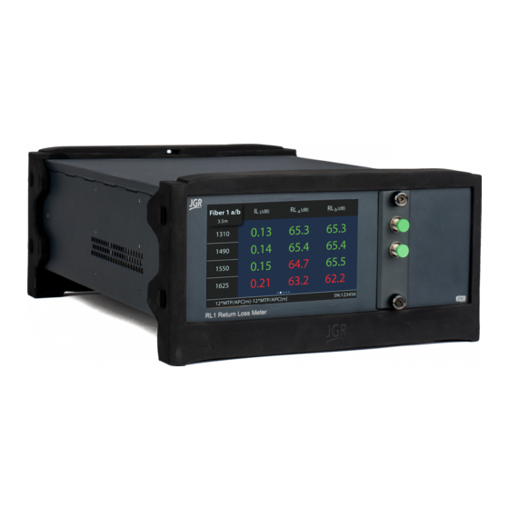
Product Overview RL1 Front Panel A front view of the RL1 meter is shown in Figure 2. It features a touchscreen which displays information such as references, measurements, test plans, setup and detectors. The FC output panel (output and input panel in the case of a 2X configuration) is located on the front of the unit. -
Page 15: Rd-S Wireless Remote-Head Detector
The RL1 comes standard with one RD-S Wireless Remote-head Detector. Additional RD-S detectors can be paired to an RL1 for more test setup flexibility. They are connected to each other in series. Figure 4 shows a front view of the RD-S. It uses a wide aperture integrating sphere cavity for maximum uniformity and is ideal for multifiber assemblies such as MPO or duplex LC. - Page 16 Connection to next RD-S (if pairing multiple RD-S) Micro-USB port • Charging port M12 connector • Connection to RL1 (or preceding RD-S if pairing multiple RD-S) LED indicator • Green: RD-S is paired to an RL1 • Orange: RD-S is not paired to an RL1 •...
-
Page 17: Operation
RL1 User Manual OPERATION Before the RL1 meter can be used to make a measurement, the user must setup the meter and connect and reference a “test jumper” to the front panel. Powering Up the Meter To power up the meter: 1. -
Page 18: Device Information And Settings
RL1 User Manual Table 5: Detailed description of the RL1 Detectors page (see Figure 6) Item # Description Battery charge indicator RD-S serial number Press and move up/down to scroll through the paired detectors list Tap to pair a detector... -
Page 19: Selecting A Test Plan
Selecting a Test Plan Swipe right to access the Test Plan Information page (Figure 8). Scan an XN1 test plan barcode while on this screen to load the plan onto the RL1. Please refer to the XN1 Server User Manual for more information. -
Page 20: Performing A Reference
RL1 User Manual Figure 8: RL1 Test Plan Information page Performing a Reference Swipe right twice to access the Reference page. See Figure 9 and Table 7 for a detailed description. In the case of RL measurements, the test jumper length should be at least 3 meters. -
Page 21: Performing A Measurement
RL1 User Manual Table 7: Detailed description of the RL1 Reference page (see Figure 9) Item # Description Detector • Tap: go to the next detector • Press and hold: open scroll menu to select desired detector Channel • Tap: perform a full reference for that channel •... - Page 22 : connector return loss (RL) in dB at positions A and B Dual Additional information • If a software is controlling the RL1, will display message “Remote” • If an XN1 test plan is loaded, will display the DUT SN after it is scanned M-RL1-001-01...
-
Page 23: Connecting An Sx1 Switch
The RL1 can be used with a switch for multifiber or high throughput applications. 1. Connect the SX1 (USB B port) to the RL1 (USB A port). 2. On the RL1 Setup page, confirm the SX1 connectivity and, if the RL1 is a dual output, the switch assignment (see Figure 12). - Page 24 Selection pop-out. Tap to go to the next channel. Figure 13: RL1 with SX1 – Measure page 4. Swipe right to access the Reference page (see Figure 14). References are displayed and managed based on the activated switch from step 3.
-
Page 25: Rl1 Webpage
RL1 User Manual RL1 Webpage To access the RL1 webpage, connect the meter to a network and on any computer or tablet on the same network, open a web browser (recommended: Google Chrome or Firefox) and enter the RL1’s IP address (see Device Information and Settings on page 12) in the URL bar. -
Page 26: Settings
You can assign a Human Interface Device (HID) input string from the Settings > Input Strings tab (Figure 16). Note: the HID must be USB 2.0 or higher. Figure 16: RL1 webpage – Input Strings tab Table 9: Description of HID input string SCPI commands... -
Page 27: Network Settings
RL1 User Manual Network Settings You can view, edit or reset the network settings of the RL1 from the Settings > Network Settings tab (Figure 17). Figure 17: RL1 webpage – Network Settings tab Upgrade Go to Settings > Upgrade to view the version of, upgrade or re-install the firmware of the RL1 and power meters (Figure 18). -
Page 28: Self-Calibration
RL1 User Manual Figure 18: RL1 webpage – Upgrade tab Self-calibration See detailed Self-calibration section on page 25. Help Click on the Help tab (Figure 19) for the website technical support and sales contact forms as well as a link to the software downloads page. -
Page 29: About
RL1 User Manual Figure 19: RL1 webpage – Help tab About The About tab (Figure 20) displays the unit’s firmware version, model and serial number. Advanced mode is reserved for JGR technicians and JGR-approved service centers. M-RL1-001-01... - Page 30 RL1 User Manual Figure 20: RL1 webpage – About tab M-RL1-001-01...
-
Page 31: Self-Calibration
RL1 User Manual Self-calibration The RL1 uses a new, patent pending calibration process which relies on the intrinsic properties of the fiber inside the instrument. As such, it does not require any external artifacts for calibration. For more information on this method, please visit our website or contact us at info@jgroptics.com. - Page 32 6. If one of the steps fails, see the Troubleshooting section on page 27. 7. Once the self-calibration is completed and each step was successful, click Save to store the report on the RL1 8. The saved reports can be viewed from the Dashboard tab of the RL1 webpage (see Figure 22) M-RL1-001-01...
-
Page 33: Troubleshooting
(ex: dust, dirt, water droplets, residues) • damage such as connector end-face scratches and pits or micro-cracks in the fiber Table 10 gives a description of each step and some common issues to investigate before contacting JGR Optics. M-RL1-001-01... - Page 34 Contaminated or damaged output lead connector: ➢ inspect output lead connector end-face ➢ as needed: clean and/or polish Return Loss Calibrates RL No external elements, contact JGR Optics Accuracy Optical Performs a series of self- Poor fiber management: ➢ verify the output lead and the test jumper do not...
- Page 35 RL1 User Manual Figure 23: Example of good test jumper fiber management M-RL1-001-01...
-
Page 36: Programming Guide
Connect the RL1 to the network via an Ethernet cable • Swipe on the front panel touchscreen to the Setup page to view the RL1’s IP address The TCP/IP libraries provided by most operating systems are sufficient. JGR Optics can provide a communications library upon request. -
Page 37: Notes
1. Some commands (ex: READ:RL? in Standard mode) can take several seconds to return. The Read timeout should be increased to at least 5000ms using visa.TimeoutMilliseconds 2. The RL1 runs SCPI commands synchronously. An *OPC? command can be sent and a 1 will be returned when all operations have been completed: Query("LAS:ENAB "... - Page 38 RL1 User Manual Table 11: Standard SCPI required commands list *CLS *ESE # *ESE? *ESR? *IDN? *OPC *OPC? *OPT? *RCL ”filename” *RST *SAV ”filename” *SRE # *SRE? *STB? *TST? *WAI :STATus:OPERation:CONDition? :STATus:OPERation:ENABle <byte> :STATus:OPERation:ENABle? :STATus:OPERation[:EVENt]? :STATus:QUEStionable:CONDition? :STATus:QUEStionable:ENABle <byte> :STATus:QUEStionable:ENABle? :STATus:QUEStionable[:EVENt]?
- Page 39 Set <length> of MTJ1 for the current channel (use output and/or switch commands to set the current channel). REF:RL? Return MTJ1 length stored in the RL1 for the current channel (use output and/or switch commands to set the current channel). POW:det#:INFO? Return serial number, calibration date, FW version, battery level, and connection type for paired detector <#>.
- Page 40 Start looking for auto-start conditions on specified <nominal wavelength, detector #>. READ:BARCode? Return a string with the contents of the last barcode scanned. TEST:NOTIFY# "string" Push a <notification> to the RL1 touchscreen display. # indicates the icon to be displayed: • • •...
-
Page 41: Maintenance
3. Gently remove the output panel. Ensure a clear line of sight to the fiber to prevent any stress on the output fiber. 4. Remove the connectors from the mating sleeves. For multiple output RL1’s, a marking is visible on the fiber to distinguish which fiber is used for which output. - Page 42 RL1 User Manual resistance or twisting. Figure 26 shows an exposed view of good output fiber management. Figure 27 shows poor fiber management. Figure 24: Dirty connector end-face inspection using Figure 25: Clean connector end-face inspection using JGR's CS400K JGR's CS400K...
-
Page 43: Cleaning Jumper Connectors
RL1 User Manual Note: the exposed views are only for instructional purposes. The RL1 chassis should not be opened during normal maintenance. Cleaning Jumper Connectors Warning • Using contaminated or damaged jumpers can affect the performance of the unit. •... -
Page 44: Storage And Shipping
As indicated above, please ship the returned material in the original shipping box and packing material. If these are not available, follow the guidelines below: 1. Contact JGR Optics to obtain an RMA number. 2. Cover the front panel with foam to prevent damage. -
Page 45: Specifications
RL1 User Manual Specifications Table 13: RL1 optical and electrical specifications sheet M-RL1-001-01... - Page 46 RL1 User Manual Table 14: RL1 mechanical and environmental specifications sheet M-RL1-001-01...
Need help?
Do you have a question about the RL1 and is the answer not in the manual?
Questions and answers