Table of Contents
Advertisement
Quick Links
Advertisement
Table of Contents

Subscribe to Our Youtube Channel
Related Manuals for JGR BR1


Summary of Contents for JGR BR1
- Page 1 BR1 Backreflection Meter User Manual...
- Page 2 BR1 User Manual All information contained herein is believed to be accurate and is subject to change without notice. No responsibility is assumed for its use. © JGR Optics Inc., 2020. All rights reserved. M-BR1-001-01...
-
Page 3: Table Of Contents
FDA-CDRH Compliance ..........................1 CSA / IEC Compliance ..........................1 CE Compliance ............................1 GENERAL INFORMATION .................... 2 BR1 Backreflection Meter Overview......................2 Applications ............................... 2 Key Features .............................. 2 Test & Measurement Standards ........................ 3 Included Accessories ..........................3 Optional Accessories .......................... - Page 4 Notes ............................... 22 Commands Lists............................22 MAINTENANCE ......................25 Cleaning the Unit ............................. 25 Cleaning the Output ..........................25 Cleaning Jumper Connectors ........................27 STORAGE AND SHIPPING ..................28 Returning Instruments to JGR Optics ...................... 28 Contact Information ..........................28 SPECIFICATIONS ......................29 M-BR1-001-01...
-
Page 5: List Of Figures And Tables
Table 1: Safety symbols..........................4 Table 2: Environmental requirements ......................8 Table 3: Detailed description of the BR1 rear panel components (see Figure 3) ......... 9 Table 4: Detailed description of the BR1 Setup page (Figure 4) ..............11 Table 5: SCPI required commands list ......................23 Table 6: BR1 commands list ........................ -
Page 6: Compliance
BR1 User Manual COMPLIANCE FDA-CDRH Compliance Under the US Food and Drug Administration (FDA) Center for Devices and Radiological Health (CDRH), the unit complies with the Code of Federal Regulations (CFR), Title 21, Subchapter J, which pertains to laser safety and labeling. See following link for more information: •... -
Page 7: General Information
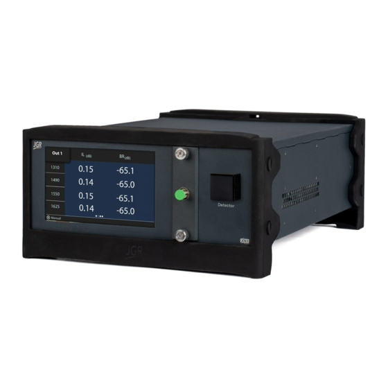
BR1 User Manual GENERAL INFORMATION BR1 Backreflection Meter Overview The BR1 Backreflection Meter is a user-friendly instrument developed with extremely stable optics for precise measurement of backreflection, insertion loss and power. Figure 1: BR1 Backreflection Meter Applications • Component testing •... -
Page 8: Test & Measurement Standards
BR1 User Manual Test & Measurement Standards • IL conforms to IEC 61300-3-4 and IEC 61280-4-1 • Multimode IL launch conditions meet the IEC 61280-4-1 Encircled Flux standard • BR conforms to IEC 61300-3-6 Included Accessories • USB A to USB B cable (1.8m) •... -
Page 9: Safety Information
Classification The BR1 consists of an exposed metal chassis that is connected directly to earth via a power cord and is therefore classified as a Class 1 instrument. The laser (or lasers) contained in the BR1 is (are) Class 1 laser(s) as specified under the laser classification of the US Food and Drug Administration (FDA) Center for Devices and Radiological Health (CDRH). -
Page 10: Important Safety Information
BR1 User Manual CLASS 1 LASER PRODUCT Important Safety Information Laser Hazards Warning • Never look directly into the end of an optical cable connected to an optical output device that is operating. Laser radiation is invisible and direct exposure can severely injure the human eye. - Page 11 If the equipment is used in a manner not specified by the manufacturer, the protection provided by the equipment may be impaired. Only technicians authorized by JGR Optics Inc. should carry out repairs. In addition to voiding the warranty, opening the unit (even when unplugged) can expose you to potential shock hazards.
-
Page 12: Getting Started
INFORMATION on page 4. This manual contains complete operating instructions for safe and effective operation of the BR1 Backreflection Meter. It is recommended that users of the BR1 familiarize themselves with contents of this manual before using the instrument. The inspection report and a description of any customer-requested information may be found in the calibration document envelope included with the instrument. -
Page 13: Product Overview
Product Overview BR1 Front Panel A front view of the BR1 meter is shown in Figure 2. It features a touchscreen which displays information such as references, measurements and setup. The FC/APC output panel is located on the front of the unit. - Page 14 BR1 User Manual Figure 3: Rear view of a BR1 Table 3: Detailed description of the BR1 rear panel components (see Figure 3) Item # Description LAN/Reset • Press once: reset network settings • Press and hold for > 5 seconds: restore previous version firmware version...
-
Page 15: Operation
BR1 User Manual OPERATION Before the BR1 meter can be used to make a measurement, the user must setup the meter and connect and reference a “test jumper” to the front panel. Powering Up the Meter To power up the meter: 1. -
Page 16: Performing A Reference
BR1 User Manual Table 4: Detailed description of the BR1 Setup page (Figure 4) Parameter Description • If connected to a network via Ethernet, it will show as Connected. Network Status: • If not connected to a network, it will show as Disconnected. - Page 17 BR1 User Manual Figure 5: BR1 Reference page – no stored references A pause window will appear for a BR reference with a live reading (Figure 6). The BR measurement range is limited to within 15 dB of the BR reference.
-
Page 18: Performing An Il And Br Measurement
BR1 User Manual The reference page (Figure 7) will display the stored values. Figure 7: BR1 Reference page – stored values Performing an IL and BR Measurement Swipe left to access the Measure page. Tap on a wavelength to display a live reading at that wavelength (Figure 8). -
Page 19: Performing An Absolute Power Measurement
Figure 9: BR1 Measure page – measurement complete Performing an Absolute Power Measurement Swipe right twice to access the Absolute Power page (Figure 10). Tap on a wavelength to display a live reading. Figure 10: BR1 Absolute Power page – live reading M-BR1-001-01... - Page 20 BR1 User Manual Tap in the center to perform a full measurement on all wavelengths (Figure 11). Figure 11: BR1 Absolute Power page – measurement complete M-BR1-001-01...
-
Page 21: Br1 Webpage
BR1 User Manual BR1 WEBPAGE To access the BR1 webpage, connect the meter to a network and on any computer or tablet on the same network, open a web browser (recommended: Google Chrome or Firefox) and enter the BR1’s IP address (see Device Information and Settings on page 10) in the URL bar. -
Page 22: Network Settings
Figure 13: BR1 webpage – Network Settings tab Upgrade Go to Settings > Upgrade to view the version of, upgrade or re-install the firmware of the BR1 (Figure 14). Please contact support@jgroptics.com before performing a firmware upgrade for additional instructions. -
Page 23: Help
BR1 User Manual Figure 14: BR1 webpage – Upgrade tab Help Click on the Help tab (Figure 15) for the website technical support and sales contact forms. Alternatively, email support@jgroptics.com for technical support or info@jgroptics.com for sales and other inquiries. -
Page 24: About
BR1 User Manual Figure 15: BR1 webpage – Help tab About The About tab (Figure 16) displays the unit’s firmware version, model and serial number. Advanced mode is reserved for JGR technicians and JGR-approved service centers. M-BR1-001-01... - Page 25 BR1 User Manual Figure 16: BR1 webpage – About tab M-BR1-001-01...
-
Page 26: Programming Guide
Connect the BR1 to the network via an Ethernet cable • Swipe on the front panel touchscreen to the Setup page to view the BR1’s IP address The TCP/IP libraries provided by most operating systems are sufficient. JGR Optics can provide a communications library upon request. -
Page 27: Notes
1. Some commands can take several seconds to return. The Read timeout should be increased to at least 5000ms using visa.TimeoutMilliseconds 2. The BR1 runs SCPI commands synchronously. An *OPC? command can be sent and a 1 will be returned when all operations have been completed: Query("LAS:ENAB "... - Page 28 Initiates the internal self-test and returns the results: 0 if all tests passed and 1 if at least one failed. *WAI Causes instrument to wait until all commands are completed. Table 6: BR1 commands list Command Description LASer:DISABle Disables all lasers.
- Page 29 Sets internal IL compensation (1 = enabled, 0 = disabled). LASer:COMPensate? Return IL compensation setting. READ:BARCode? Returns a string with the contents of the last barcode scanned. TEST:NOTIFY# “string” Push a <notification> to the BR1 touchscreen display. <#> indicates the icon to be displayed: • • • •...
-
Page 30: Maintenance
3. Gently remove the output panel. Ensure a clear line of sight to the fiber to prevent any stress on the output fiber. 4. Remove the connectors from the mating sleeves. For multiple output BR1’s, a marking is visible on the fiber to distinguish which fiber is used for which output. - Page 31 BR1 User Manual resistance or twisting. Figure 19 shows an exposed view of good output fiber management. Figure 20 shows poor fiber management. Figure 17: Dirty connector end-face inspection using Figure 18: Clean connector end-face inspection using JGR's CS400K JGR's CS400K...
-
Page 32: Cleaning Jumper Connectors
BR1 User Manual Note: the exposed views are only for instructional purposes. The BR1 chassis should not be opened during normal maintenance. Cleaning Jumper Connectors Warning • Using contaminated or damaged jumpers can affect the performance of the unit. •... -
Page 33: Storage And Shipping
As indicated above, please ship the returned material in the original shipping box and packing material. If these are not available, follow the guidelines below: 1. Contact JGR Optics to obtain an RMA number. 2. Cover the front panel with foam to prevent damage. -
Page 34: Specifications
BR1 User Manual SPECIFICATIONS Table 7: BR1 optical and electrical specifications sheet Specification Parameter Single-mode Multimode Fiber Type (μm) 9/125 50/125 or 62.5/125 Encircled Flux Standard IEC 61280-4-1 1310 / 1490 / 1550 / 1625 / Operating Wavelengths (nm) 850 / 1300... - Page 35 BR1 User Manual Table 8: BR1 mechanical and environmental specifications sheet Parameter Specification Unit Dimensions W x H x D (cm) 23.5 x 12 x 32.5 Shipping Box Dimensions W x H x D (cm) 36.5 x 39 x 53...
Need help?
Do you have a question about the BR1 and is the answer not in the manual?
Questions and answers