
Related Manuals for Alfa Laval FrontLine ClipLine


Summary of Contents for Alfa Laval FrontLine ClipLine
- Page 1 Gasketed plate heat exchangers FrontLine™ ClipLine® Instruction Manual Lit. Code 200000420-4-EN-GB...
- Page 2 © Alfa Laval Corporate AB 2020-03 This document and its contents are subject to copyrights and other intellectual property rights owned by Alfa Laval Corporate AB. No part of this document may be copied, re-produced or transmitted in any form or by any means, or for any purpose, without Alfa Laval Corporate AB’s prior express written permission. Information and services provided in this document are made as a benefit and service to the user, and no representations or warranties are made about the accuracy or suitability of this information and these services for any purpose.
- Page 3 English Magyar Download local language versions of this instruction Az Ön nyelvére lefordított használati útmutatót manual from www.alfalaval.com/gphe-manuals or use letöltheti a www.alfalaval.com/gphe-manuals the QR code weboldalról, vagy használja a QR-kódot. български Italiano Изтеглете версиите на това ръководство за Scarica la versione in lingua locale del manuale di употреба...
- Page 4 Pусский Руководство пользователя на другом языке вы можете загрузить по ссылке www.alfalaval.com/ gphe-manuals или отсканировав QR-код. Slovenski Prenesite različice uporabniškega priročnika v svojem jeziku s spletne strani www.alfalaval.com/gphe- manuals ali uporabite kodo QR. Slovenský Miestne jazykové verzie tohto návodu na používanie si stiahnite z www.alfalaval.com/gphe-manuals alebo použite QR kód.
-
Page 5: Table Of Contents
Contents 1 Introduction ........................7 Intended use......................7 Reasonably foreseeable misuses................7 Prior knowledge......................7 Delivered technical information................. 8 Warranty conditions....................8 Advice........................8 Environmental compliance..................9 2 Safety ..........................11 Safety considerations....................11 Definitions of expressions..................11 Personal protective equipment................12 Working at height.....................13 3 Description ........................15 Components...................... - Page 6 5 Operation ........................45 Start-up........................45 Unit in operation...................... 47 Shut-down....................... 47 6 Maintenance ......................49 Cleaning – Product side..................50 Cleaning – Non-product side...................53 Opening........................55 6.3.1 Bolt configuration..................55 6.3.2 Opening procedure..................55 Manual cleaning of opened units................59 6.4.1 Deposits removable with water and brush..........59 6.4.2 Deposits not removable with water and brush...........
-
Page 7: Introduction
The intended use of this equipment is to transfer heat in accordance with a decided configuration. All other use is prohibited. Alfa Laval will not be held responsible for injury or damage if the equipment is used for any other purpose than the intended use described above. -
Page 8: Delivered Technical Information
If faults occur during the specified warranty period, always consult your local Alfa Laval representative for advice. Report to the local Alfa Laval representative, the date when the plate heat exchanger was put into operation . 1.6 Advice Always consult your local Alfa Laval representative for advice on: •... -
Page 9: Environmental Compliance
If there is any uncertainty regarding what material a component is made of, contact the local Alfa Laval sales company. Use a certified (ISO 14001 or similar) scrapping or waste handling company. - Page 10 1 Introduction 200000420-4-EN-GB...
-
Page 11: Safety
2.1 Safety considerations The plate heat exchanger shall be used and maintained in accordance with Alfa Laval’s instructions in this manual. Incorrect handling of the plate heat exchanger may result in serious consequences with injuries to persons and/or property damage. Alfa Laval will not accept responsibility for any damage or injury resulting from not following the instructions in this manual. -
Page 12: Personal Protective Equipment
2 Safety 2.3 Personal protective equipment Protective shoes A shoe with a reinforced toe cap to minimize foot injuries caused by dropped articles. Protective helmet Any helmet designed to protect the head from accidental injury. Protective goggles A pair of tight-fitting eyeglasses worn to protect the eyes from hazards. Protective gloves Gloves that protects the hand from hazards. -
Page 13: Working At Height
Safety 2 2.4 Working at height If the installation requires working at a height of two meters or higher, safety arrangements must be taken in consideration. WARNING Risk of falling. For any kind of work at height, always ensure that safe means of access is available and used. - Page 14 2 Safety 200000420-4-EN-GB...
-
Page 15: Description
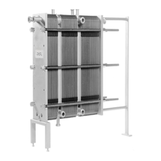
3 Description 3.1 Components 9 10 Main components 1. Frame plate Fixed plate with a various number of portholes for the connection of the piping system. The carrying and guiding bar are attached to the frame plate. 2. Carrying bar Carries the plate pack and the pressure plate 3. - Page 16 3 Description 9. Corner connections Pipes with sanitary fittings or flanges allow the media to enter into or exit from the plate heat exchanger. 10. Connection plate A plate with corner connections for the connection of the piping system. A connection plate divides the plate package into sections allowing two or more heat transfer processes in one plate heat exchanger.
-
Page 17: Name Plate
Description 3 3.2 Name plate The type of unit, manufacturing number and manufacturing year can be found on the name plate. Pressure vessel details in accordance with the applicable pressure vessel code are also given. The name plate is fixed to the frame plate, most commonly, or the pressure plate. - Page 18 3 Description Manufacturer Type Serial No. MANUFACTURER: Year YEAR OF MANUFACTURING: Fluid group TYPE: SERIAL NUMBER: Inlet Outlet Volume → → Allowable press. INLET → OUTLET Min./Max. FLUID GROUP VOLUME Allowable temp. MAX. OP. TEMP. Min./Max. TS ALLOWABLE PRESS. Manufacturer MIN./MAX.
-
Page 19: A Measure
Description 3 3.3 A measure The A measure is the distance from the frame plate (1) to the pressure plate (2). 200000420-4-EN-GB... -
Page 20: Function
3 Description 3.4 Function The plate heat exchanger consists of a pack of corrugated metal plates with portholes for the input and output of the two separate fluids. The heat transfer between the two fluids takes place through the plates. The plate pack is assembled between a frame plate and a pressure plate and compressed by tightening bolts. -
Page 21: Multi-Section
Description 3 3.5 Multi-section A multi-section plate heat exchanger can be set up by using connection plates. An example of multi-section configuration is when a media needs to be heated in one stage and then cooled down in the next stage. Each of the connection plates can be configured by selecting different corner connections such as single, double, pass-through or blind. -
Page 22: Multi-Pass
3 Description 3.6 Multi-pass Multi-pass sections can be created by using turning plates with 1, 2 or 3 unholed ports. The main purpose is to change the flow direction of one or both fluids. An example of where multi-pass can be used is in processes that require longer heating periods if the media requires slower heating. -
Page 23: Installation
4 Installation 4.1 Before installation, lifting and transport CAUTION Risk of damage to equipment. During installation or maintenance, precautions must be taken to avoid damaging the plate heat exchanger and its components. Damage to components can adversely affect the performance or serviceability of the plate heat exchanger. - Page 24 4 Installation • Follow the hierarchy specified in this presentation. • Check the condition of the flooring. • Always complete a risk assessment. • Use frames and equipment designed for the task. • Always check the center of gravity before unpacking or moving the equipment.
-
Page 25: Requirements
Installation 4 4.2 Requirements Space See the delivered PHE drawing for actual measurements. 1. Free space is required for lifting plates in and out. 2. Free space is required for removing the tightening bolts. The size is depending on the length of the tightening bolts. 3. - Page 26 4 Installation CAUTION Risk of damage to equipment. Turning of the connections will damage the gaskets on the end plate and cause leakage. Fit the pipes so that no tension is transferred to the plate heat exchanger. Nozzle loads are not permitted. Pipes connected to the pressure plate and to the connection plates must allow ±1% of the distance from the connection to the frame plate (see the assembly PHE drawing).
-
Page 27: Crate Handling
Installation 4 4.3 Crate handling WARNING Risk of personal injury. Lifting and transport of the crated and uncrated equipment must be carried out by skilled persons. See Prior knowledge in Chapter Preface. The plate heat exchanger is delivered on a pallet and can be packed in a crate or wrapped in stretch film. -
Page 28: Crate - Inspection
4 Installation 4.3.1 Crate — Inspection Examine the outside of the crates before starting to unload and report any transport damage. Contact the insurance company in case of any damages. 4.3.2 Lifting and transportation WARNING Risk of personal injury. The equipment is heavy and sensitive and must be handled with precaution. - Page 29 Installation 4 • The length of the forklift forks should be equal to, or longer than, the depth of the pallet. • Make sure that the crate remains stable on the lifting equipment. • Move the crate to its destination. •...
-
Page 30: Unpacking The Crate
4 Installation 4.4 Unpacking the crate Follow the procedure for the corresponding type of crate:: • Manufactured sides — See Procedure Manufactured sides - Open • Flip box — See Procedure Flip box - Opening • Crafted sides — See Procedure Crafted sides - Opening Unpacking area The minimum unpacking area must be at least twice the size of the largest... -
Page 31: Manufactured Sides - Opening
Installation 4 4.4.1 Manufactured sides — Opening WARNING Risk of personal injury. The equipment or loose objects can fall. Plastic straps may snap when cut off. There can be sharp edges, splinters, and nails on the crate and the equipment. Wear personal protective equipment when handling the equipment during unpacking and installation. -
Page 32: Flip Box - Opening
4 Installation 4.4.2 Flip box — Opening WARNING Risk of personal injury. The equipment or loose objects can fall. Plastic straps may snap when cut off. There can be sharp edges, splinters, and nails on the crate and the equipment. Wear personal protective equipment when handling the equipment during unpacking and installation. -
Page 33: Crafted Sides - Opening
Installation 4 4.4.3 Crafted sides — Opening WARNING Risk of personal injury. The equipment or loose objects can fall. Plastic straps may snap when cut off. There can be sharp edges, splinters, and nails on the crate and the equipment. Wear personal protective equipment when handling the equipment during unpacking and installation. -
Page 34: Inspection After Uncrating
4 Installation 4.4.4 Inspection after uncrating When the equipment is placed in its intended location, always perform the inspections listed below: • Check the A measure. • Make sure that all bolts are properly tightened. • Make sure that the stands and feet are properly tightened. NOTE Some equipment is delivered with the stands disassembled. -
Page 35: Lifting The Equipment
Installation 4 4.5 Lifting the equipment It is recommended to engage the services of a rigging company to take care of all handling related matters until the equipment is in the position where it will be installed. WARNING Risk of personal injury. Equipment is heavy with a centre of gravity placed high. - Page 36 4 Installation Crated equipment When the equipment is crated it must be lifted in the delivered pallet using a forklift. Disassemble equipment from pallet Uncrate the equipment according to Section Installation - Unpacking the crate. It is recommended to let the equipment remain assembled with the pallet and handle it using a forklift until it is time to install it.
- Page 37 Installation 4 Before loosening the equipment from the pallet, secure the equipment from falling using hoist slings. NOTE Do not lift up the equipment and the pallet. Only stretch the hoist slings so the equipment will not fall. Remove any attachment that assembles the equipment with the pallet. Gently lift up the equipment and make sure that it releases from the pallet.
- Page 38 Use of other attachment points or strap load directions than those described are not allowed. If the plate heat exchanger is not supplied with lifting devices from Alfa Laval, the corresponding equipment must be selected and the same attachment points must be used.
- Page 39 Installation 4 200000420-4-EN-GB...
-
Page 40: Raising
4 Installation 4.6 Raising This instruction is valid when raising the plate heat exchanger after delivery from Alfa Laval. Only use a strap approved for the weight of the plate heat exchanger. Follow the principle of the instruction below. CAUTION Risk of damage to equipment. - Page 41 Installation 4 Lift the plate heat exchanger off the timber beams. Lower the plate heat exchanger into a horizontal position and place it on the floor. 200000420-4-EN-GB...
-
Page 42: Assemble Stands
4 Installation 4.7 Assemble stands Some models of plate heat exchangers are delivered without the stands assembled. Follow the instruction below. WARNING Risk of crushing. The equipment is heavy. Be careful when handling the equipment. Do not reach in under equipment that is not secured. WARNING Risk of crushing. -
Page 43: Inspection Before Installation
Installation 4 4.8 Inspection before installation When the equipment is placed in its intended location, always perform the inspections listed below: • Check the A measure. • Make sure that all bolts are properly tightened. • Make sure that the stands and feet are properly tightened. •... - Page 44 4 Installation 200000420-4-EN-GB...
-
Page 45: Operation
5 Operation 5.1 Start-up During the start-up, check that there are no visible leakages from the plate pack, valves or piping system. CAUTION Before pressurizing the plate heat exchanger, it is important to ensure that the temperature of the plate heat exchanger is within the temperature range as stated on the name plate. CAUTION Risk of leakage. - Page 46 5 Operation Check that the valve is closed between the pump and the unit controlling the system flow rate to avoid pressure surge. If there is a vent valve installed at the exit, make sure it is fully open. Increase the flow rate slowly. Open the air vent and start the pump.
-
Page 47: Unit In Operation
Operation 5 5.2 Unit in operation Adjustments of flow rates should be made slowly in order to protect the system against sudden and extreme variations of temperature and pressure. During operation, check that media temperatures and pressures are within the limits stated on the name plate and the PHE drawing. - Page 48 5 Operation 200000420-4-EN-GB...
-
Page 49: Maintenance
50 and Cleaning – Non-product side on page 53) or reconditioning can be performed at an Alfa Laval service center. After a long period of use, it can be required to regasket the plate heat exchanger. See Procedure Regasketing on page 65. -
Page 50: Cleaning - Product Side
6 Maintenance 6.1 Cleaning – Product side Immediately after a production cycle, the product side is normally cleaned through the circulation of acid and/or lye as a built-in sequence in the production cycle. NOTE After the first test run of the product, the plate heat exchanger should be cleaned following a cleaning program applicable to the product in question. - Page 51 20°C. Treat for five minutes, up to maximum of 15 mi- nutes. Rinse well after sterilisation. Typical cleaning programs Consult your local Alfa Laval representative for advice on suitable cleaning programmes. Table 1: Coolers Products rich in protein...
- Page 52 6 Maintenance Products poor in protein Daily Weekly Rinsing 10 min Rinsing 10 min Lye 30 min Lye 30 min Rinsing 10 min Rinsing 5 min Stop Acid 15 min Sterilisation 10 min Rinsing 10 min Stop Sterilisation 10 min Table 4: Low content of insoluble components, for example beer and wine Products poor in protein Weekly...
-
Page 53: Cleaning - Non-Product Side
Personal protective equipment in Chapter Safety. CIP equipment Contact an Alfa Laval sales representative for the size of CIP equipment. WARNING Risk of personal injury. The residuals after a cleaning procedure shall be handled according to local environmental regulations. After neutralization most cleaning... - Page 54 6 Maintenance Liquid Description AlfaDescalent A non-hazardous acidic cleaning agent for the removal of inorganic scale. A non-hazardous cleaning agent for the removal of oil, grease or wax deposits. Also AlfaDegreaser prevents foaming when using Alpacon Descaler. AlfaAdd is a neutral cleaning strengthener designed to be used with AlfaPhos, Alfa- Caus and Alfa P-Scale.
-
Page 55: Opening
During manual cleaning, it is necessary to open the plate heat exchanger to clean the plates. NOTE Before opening the plate heat exchanger, check the warranty conditions. If in any doubt, contact the Alfa Laval sales representative. See Section Warranty conditions in Chapter Introduction. WARNING Risk of personal injury. - Page 56 6 Maintenance Close the valves and isolate the plate heat exchanger from the rest of the system. NOTE The plate heat exchanger must be pressureless before disconnecting it. Drain the plate heat exchanger. NOTE Avoid vacuum in the plate heat exchanger by opening vent valves.
- Page 57 Maintenance 6 Check and note the A measure. Loosen and remove the locking bolts. Identify them according to Bolt configuration on page NOTE Brush the threads of the tightening bolts with a steel wire brush and then grease the threads before loosening the tightening bolts.
- Page 58 6 Maintenance CAUTION Risk of personal injury. Plates and protection sheets has sharp edges. Wear personal protective equipment when handling the plates and the protection sheets. See Section Personal protective equipment in Chapter Safety. Open the plate pack by letting the pressure plate glide on the carrying bar.
-
Page 59: Manual Cleaning Of Opened Units
Maintenance 6 6.4 Manual cleaning of opened units CAUTION Never use hydrochloric acid with stainless steel plates. Water of more than 330 ppm Cl may not be used in the preparation of cleaning solutions. It is very important that aluminium carrying bars and support columns are protected against chemicals. -
Page 60: Deposits Not Removable With Water And Brush
6 Maintenance Rinse with water using a high pressure hose. 6.4.2 Deposits not removable with water and brush Plates must be removed from the plate heat exchanger during cleaning. For a choice of cleaning agents, see Section Cleaning liquids on page 53. Brush with cleaning agent. -
Page 61: Closing
Check that the hanger device is not damaged. Brush the threads of the bolts clean, using a steel wire brush or the Alfa Laval thread cleaner. Lubricate the threads with a thin layer of grease, for example Gleitmo 800 or equivalent. - Page 62 6 Maintenance Press the plate pack together. Position the four tightening bolts according to the illustration.Tighten the four bolts (1), (2), (3), (4) until the plate pack measure is 1.10×A making sure the frame plate and pressure plate are parallel when closing. Tighten the four bolts (1), (2), (3), (4) evenly until the A measure has been reached.
- Page 63 Maintenance 6 Install protection sheets (if provided). 10 Connect the pipes. 11 If the plate heat exchanger does not seal when the A measure has been reached, it can be tightened further to the given A measure value minus 0.5%. 200000420-4-EN-GB...
-
Page 64: Pressure Test After Maintenance
Example of a rebuilding is that more number of plates are added to the plate pack. If there is any uncertainty about the testing procedure of the plate heat exchanger, consult an Alfa Laval representative. 200000420-4-EN-GB... -
Page 65: Regasketing
6.7 Regasketing NOTE For Front 15, you must perform actions in addition to the instructions below to make the gaskets seal properly. Contact your Alfa Laval representative for advice. The procedures below concern field gaskets, ring gaskets and end gaskets. - Page 66 6 Maintenance Attach the gasket to the plate. Slip the gasket Clip-on tabs under the edge of the plate. NOTE Make sure the two gasket prongs are in the correct position. ClipGrip Repeat the procedure on all the plates that needs to be regasketed.
-
Page 67: Storage Of The Plate Heat Exchanger
The crate is not designed to be stacked. Never put a load on top of the crate. Alfa Laval delivers the plate heat exchanger ready to be put into service upon arrival, if nothing else has been agreed. If storing for longer periods of time, such as one month or longer, certain precautions should be made to avoid unnecessary damage to the plate heat exchanger. -
Page 68: Taken Out Of Service
Closing on page 61. 7. Alfa Laval recommends a hydraulic test should be carried out. The media, usually water, should be entered at intervals to avoid sudden shocks to the plate heat exchanger. It is recommended to test up to the Design Pressure.
Need help?
Do you have a question about the FrontLine ClipLine and is the answer not in the manual?
Questions and answers