Advertisement
Instruction Leaflet
Installation Instructions for ND, HND, NDC, CND,
Trip Unit and Powernet, and/or Zone Interlock
IL29C109J
E ective November 2013
Supersedes IL29C109H 09/11
Contents
Description
1.0 Introduction . . . . . . . . . . . . . . . . . . . . . . . . . . .
2.0 Installation . . . . . . . . . . . . . . . . . . . . . . . . . . . .
3.0 Manual Operation . . . . . . . . . . . . . . . . . . . . . .
Page
2
3
5
. . . . . . . . . . . . . .
5
Advertisement

Subscribe to Our Youtube Channel
Summary of Contents for Eaton ND Series
-
Page 1: Table Of Contents
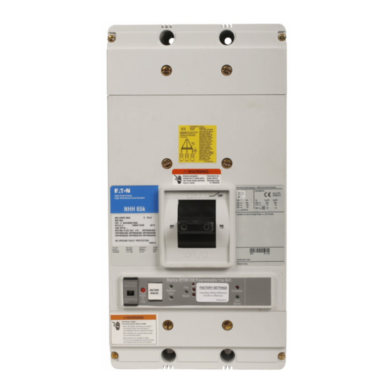
E ective November 2013 Instruction Leaflet IL29C109J Supersedes IL29C109H 09/11 Installation Instructions for ND, HND, NDC, CND, CHND, CNDC Circuit Breakers with Digitrip OPTIM Trip Unit and Powernet, and/or Zone Interlock Contents Description Page 1.0 Introduction ......2.0 Installation . -
Page 2: Chnd, Cndc Circuit Breakers With Digitrip Optim
IMPACC communications kit. nel and equipment as well as general and local health Contact Eaton for the following information and user manuals: and safety laws, codes and procedures. The recommendations and information contained herein... -
Page 3: Installation
65kA (such as NDC applica- escutcheon dimensions, see Figure 2-4. Make sure tions) the conductors are to be braced in accordance accessory wiring is accessible when the circuit breaker with Figure 2-5. is mounted. EATON CORPORATION www.eaton.com... - Page 4 Trip Unit and Powernet, and/or Zone Interlock Figure 2-2 Conductor Extensions and Terminal Installation for 100% Rating 0 31 0 31 25) Tap 4-Places Breaker Breaker 2- AND 3- -POLE Figure 2-3 Circuit Breaker Mounting Bolt Drilling Plan Table 2. EATON CORPORATION www.eaton.com...
-
Page 5: Manual Operation
ON, OFF, and trip are also shown by a color-coded strip for each circuit breaker handle position: red for ON, Circuit breakers in service should be inspected white for tripped, and green for OFF (see Figure 3-1). EATON CORPORATION www.eaton.com... - Page 6 Switch If damaged, a terminal block cover can be purchased The combination Bell Alarm Auxiliary Switch is only through Eaton. The part number is 4214844699 available on the OPTIM 1050 units. NOTICE 1. It is crucial to connect the +24 VDC power supply to the correct terminal. Improper connection can destroy the electronic protection functions of the circuit breaker.
- Page 7 Do not blow debris into Check circuit breaker mounting hardware, and tight- circuit breaker. If contamination is found, look for the en if necessary. source and eliminate the problem. Exposure to certain types of chemicals can cause EATON CORPORATION www.eaton.com...
- Page 8 Installation in order to be available to the Authority having Jurisdiction Circuit Test Date Breaker Results Tested By Number Source Load Current Limiting Resistor (if required) Figure 4- Typical Performance Test Record Form Figure 4-2 Connections for Ground Fault Trip Test EATON CORPORATION www.eaton.com...
- Page 9 ( i f r e q u i r e d ) Load Current Limiting Resistor (if required) Figure 4-3 Connections for Ground Fault No-Trip Test Figure 4-4 Connections for Ground Fault No-Trip Test with a Four- Wire System with a Three-Wire System EATON CORPORATION www.eaton.com...
- Page 10 Installation Instructions for ND, HND, NDC, CND, Instruction Leaflet IL29C109J CHND, CNDC Circuit Breakers with Digitrip OPTIM E ective November 2013 Trip Unit and Powernet, and/or Zone Interlock Notes: EATON CORPORATION www.eaton.com...
- Page 11 Installation Instructions for ND, HND, NDC, CND, Instruction Leaflet IL29C109J CHND, CNDC Circuit Breakers with Digitrip OPTIM E ective November 2013 Trip Unit and Powernet, and/or Zone Interlock Notes: EATON CORPORATION www.eaton.com...
- Page 12 AND DESCRIPTIONS CONTAINED HEREIN. In no event will Eaton be responsible to the purchaser or user in contract, in tort (including negligence), strict liability or otherwise for any special, indirect, incidental or consequential damage or loss whatsoever, including but not limited to damage or loss of use of...


Need help?
Do you have a question about the ND Series and is the answer not in the manual?
Questions and answers