Advertisement
Quick Links
Advertisement

Related Manuals for ZPA Pecky, a.s. MODACT MOED EEx Series


Summary of Contents for ZPA Pecky, a.s. MODACT MOED EEx Series
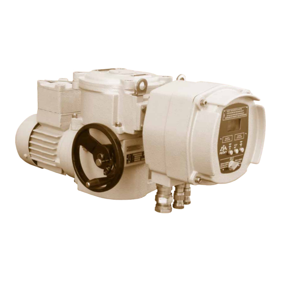
- Page 1 Electric rotary multi-tur n actuators Explosion-proof design Typ e n umber s 52 120 - 51 125 11/11...
- Page 3 The Mounting and Operating Instructions specify basic principles for mounting, connection, adjustment, opera- tion, maintenance, and repairs of electric explosion-proof actuators. A fundamental prerequisite is that assembly, operation, maintenance, and revisions are performed by skilled technicians qualified for operation and works on explosion-proof electric devices and the works are supervised by a professionally qualified expert instructed in a demonstrable way.
- Page 4 Designation of explosion-proof properties It consists of the following symbols: Electric device complies with the standard ČSN EN 60 079-0 and related standards for various types of protection against explosion. Designation of the type of protection against explosion, explosion-proof closure according to ČSN EN 60 079-1.
- Page 5 b) explosion-proof closure “d” of terminal box with block of local control and display 6) Plate with marked manufacturer and manufacturer's address. 2) OPERATING CONDITIONS, OPERATING POSITION Operating conditions the MODACT MOED EEx actuators should withstand the effect of operating conditions and external influences, Classes AA7, AB7, AC1, AD5, AE5, AF2, AG2, AH2, AK2, AL2, AM2, AN2, AP3, BA4, BC3 and BE3N2, according to ČSN Standard 33 2000-3.
- Page 6 Operating position ® Working position of actuators MODACT MOED EEx actuators with plastic lubricant – any position. The actuators with plastic lubricant are labelled “Filled: solid grease” on the power box at the side of the hand-wheel. Actuators with oil charge – position limited only by slope of electric motor axis – max. 15° under the horizontal level.
- Page 7 4) TECHNICAL DATA Supply voltage The actuators have been designed to operate at supply voltage of 3 AC 400 V / 50 Hz. However, they are available in design variants operating at another three-phase AC supply voltage, upon special request. The supply voltage of the electric motor should be within the tolerance limits of ±10 % of the rated value and the supply voltage frequency should be within ±2 % of the rated value.
- Page 8 5) ACTUATOR OUTFIT Anti-condensation heater The actuators are fitted with an anti-condensation heater preventing condensation of water vapour. It is connected to the AC mains of voltage 230 V. Local control Local control serves for controlling the actuator from the site of its installation. It includes two change-over switches: one with positions “Remote control - Off - Local control”, the other “Open - Stop - Close”.
- Page 9 Shape A (with adapter), according to ISO 5210 and DIN 3210 Shape B1 (with adapter), according to ISO 5210 (shape B according to DIN 3210) Shape B3 (without adapter), according to ISO 5210 (shape E according to DIN 3210) Shape D (without adapter), according to DIN 3210 Shape C (without adapter), according to DIN 3338...
- Page 10 The sensor of the output shaft position is absolute and does not require any backup power supply in case supply voltage is disconnected during operation of the electric actuator. Both systems can be set and monitored by a computer with controlling program (set parameter can be backed up on a computer) or manually without a computer (for the electronics DMS2, parameters can be manually set and it can be checked without computer only if the system is equipped with a display and local control).
- Page 11 Relay MO, MZ, PO, PZ DMS2 ED DMS2 ED Control elay torque open motor open (also changes-over to errors) torque closed motor close (also changes-over to errors) torque open (also changes-over to errors ) + optional position open tripping in position open (parameter Tripping) torque closed (also changes-over to errors ) + optional position closed tripping in position closed (parameter Tripping)
- Page 12 Parametr – Parameter Změna – Change Chyba – Error Přístup – Access Setrvačnost (0,1 %) – Inertia [0.1 %] Setr. Doběh (0,1 s) – Inertial run-out [0.1 s] Necitlivost (%) – Insensitivity [%] NE – NO PROCEDURE OF SETTING PARAMETERS BY MEANS OF PUSH-BUTTONS For simple programming of required operating parameters, the control unit is fitted with four push-buttons: MENU, P, O, C and three signal lamps.
- Page 13 Parameters that can be changed by user are set by manufacturer as follows: 1. Tripping torques: 100 % or required value (it is not recommended to change the value without consulting the supplier of the valve, etc.). 2. Relay 3 and relay 4: signalization SZ 1 % and SO 99 % of stroke 3.
- Page 14 MENU 6 – Setting insensitivity in three-position regulation – Shortly press P to select value 1 – 10 % (1 – 10x blinking of LED2) and keep pressing push-button P to store the parameter to memory. MENU 7 – Response in case of losing control signal in three-position regulation –...
- Page 15 Record of position CLOSED: – In the required position, press push-button Z in the program and confirm the approved record. Record of position OPEN: – In the required position, press push-button O in the program and confirm the approved record. The recorded values are confirmed by pressing push-button START in program DMS2.
- Page 16 List of warnings and errors Name Warning Error Description Safe * Input Safe activated Control signal Value of control signal ≤ 3 mA (it applies to ranges 4 – 20/20 – 4 mA) Torque Induced torque beyond end-limit positions or disconnected torque sensor Thermal protection Thermal protection input activated Sense of rotation...
- Page 17 Wiring diagram of electronics DMS2 ED in version Substitution of electro-mechanical board E0021 Local control Místní ovládání off local remote OPEN STOP STOP CLOSE E0021 Position Snímač polohy sensor Motor motor Passive output Pasívní výstup otevírej “open” MENU Motor motor “close”...
- Page 20 DMS2 Main properties of DMS2: – Complete control of the actuator run of the two- and three-position regulation or connection to the industrial bus Profibus. – Synoptic signalization of operation and service data on the character LCD display 2 x 12. –...
- Page 21 Working torque – Check and, if necessary, set the value of the working torque 50 – 100 % in program DMS2. Tripping in end-limit positions – Check and, if necessary, set the way of tripping in the end-limit positions:: – Torque –...
- Page 22 Autodiagnostics The table List of errors – same as for electronics DMS2 ED (page 16) Memory of number of induced errors – For all detected errors, DMS2 uses the counter of occurrence of these errors during operation of the system. –...
- Page 23 Name Parameter value Meaning SAFE AKTIV. Active signal Safe 230 V blokuje SAFE TP SAFE Response with thermal protection activated SAFE aktivni AUTOMATICKY TP NULOVANI Zeroing of thermal protection MISTNIM OVL. VYPNUTO VAROVANI CHYBY RELE READY VAR.+CHYBY Function of Relay Ready CHYBY+NENÍ...
- Page 24 Setting actuator by means of push-buttons: – Shift the change-over switch of local control to position OFF – Keep pressing push-button STOP to enter the MENU. Using push-buttons O or Z, browse through the MENU (MENU1 – MENU27). Shortly press push-button STOP in a selected menu to enter this menu and, using push- -buttons O or Z, select the parameter.
- Page 25 Terminal board of DMS2 Analog Terminal board of DMS2 Profbus...
- Page 26 DMS2 - local control and display Note: The setting program enables data to be copied from the memory of parameters of the electronics DMS2 and DMS2 ED into the computer as a file with suffix “par” (in the example in the figure the file 52 030.par is created in the directory Flash).
- Page 29 Table 1 – MODACT MOED EEx with AVM electric motors – basic technical parameters and designs Basic outfit: 1 electric motor type AVM 1 anti-condensation heater Torque [Nm] Adjusting Working Electric motor Weight [kg] Type number speed stroke Type designation Design Power Speed...
- Page 30 Table 2 – MODACT MOED EEx with 4KTC electric motors – basic technical parameters and designs Basic outfit: 1 electric motor type 4KTC 1 anti-condensation heater Torque [Nm] Adjusting Working Electric motor Weight [kg] Type number speed stroke Type designation Design Type Power...
-
Page 31: Table Of Contents
Explosion – proof electric rotary multi-turn actuators MODACT MOED EEx Place in the type number Type number place of type number: Table 3 – Connecting dimensions Shape A Connecting dimensions Shape B according ISO and DIN Shape C Shape D Shape E Connection M Connecting dimensions... -
Page 32: Th Place Of Type Number
place of type number: Table 7 – Ambient temperatures For ambient temperature of -25 °C to +55 °C without designation For ambient temperature of -50 °C to +55 °C *) *) The electronic outfit should be discussed with the manufacturer. Table 8 –... -
Page 33: Type Number 52
Dimensional sketch of MODACT MOED EEx electric actuator 2 x M25 x 1,5, cable ø 13 – 18 Dimensions of cable entries 1 x M20 x 1,5, cable ø 10 – 14 of electric motors are shown in Table no. 8, page 32 Type number Dimension 52 120... -
Page 34: Type Number 52 121 And 52
Holes for additional attachment of MODACT MOED EEx electric actuator Type number Dimension 52 120 52 121, 2 52 123, 4 52 125 M 10 M 12 M 16 M 20 Note: The holes intended for additional attachment of MODACT electric actuators only serve for supporting the actuator weight and may not be subjected to load with any additional force. -
Page 35: Shape A
Attachment dimensions of MODACT MOED EEx electric actuators (basic design without adapter) The electric actuators are designed for direct mounting onto the controlled device (valve etc.). They are attached by means of a flange or clutch according to ČSN 186314. The flanges of the electric actuators also comply with ISO 5210. The clutches for transmission of motion to the valve are: Shape A (with adapter), according to ČSN EN ISO 5210 (13 3090) - Page 36 Table of connecting dimensions of the MODACT MOED EEx electric actuators (without adapters) Type number / Flange Dimension Shape 52 120 52 121, 2 52 123, 4 52 125 ø d1 (orientation value) ø d2 f8 ø d3 M 10 M 16 M 20 M 16...
- Page 37 Adapters to MODACT MOED EEx electric actuators Shape A Shape B1 according to ČSN EN ISO 5210 according to ČSN EN ISO 5210 (13 3090) (13 3090) ø d5 ø d6 ø d2 ø d5 ø d3 ø d2 ø d1 ø...
- Page 38 8) ASSEMBLING AND PUTTING THE ELECTRIC ACTUATOR INTO OPERATION Upon receipt of the actuator from the factory, it is essential to check that no damage was caused during transport and to compare the data on the actuator rating plates with those contained in the order and accompanying documen- tation.
- Page 39 Instruction for Use no. N740052 – issue no.1 Non-explosive cable bushings, type leG 623 Assembly Instructions for cable gland: ICG 623 Exd IIC/Exe II Assembly Instructions Certifi cate BASEEFA No. BAS 01 ATEX 2079X (Ex) II 2 GD IP66 CE 623 EExd I/EExe I AI 305 / Issue L - 08/06 Certifi...
- Page 40 Tape Remove surplus compound Remove Compound surplus Remove compound surplus compound With all gaps and voids fi lled, bring Replace the entry (5) over the rubber Locate and hand tighten the sub-as- the conductors back together and pot (4) ensuring that compound does sembly (1) and (2) to the entry (5).
- Page 41 EPOXY COMPOUND PREPARATION When handling this material, the gloves supplied must be worn. The epoxy compound is supplied in the form of a two part package. These should be mixed into the ratio of I: I until both colours have blended into one, without any streaks.
- Page 42 3.0. Insulating drainwireswith insulating varnish or paint 3.1. Fold back the armour I braid and bend it at right angles from the inner sheath. 3.2. Remove the foil and tape level with the inner sheath exposing the drain wires and conductor pairs. 3.3.
- Page 43 Limiting conditions: 1. Cable bushings OS and O can only be used for braided cables and firm instruments; the cable should be properly fixed to prevent its possible pulling out or twisting. 2. Operating temperature of the cable bushing is -60 °C to +80 °C. 3.
- Page 44 Lubricants Surrounding temperature [°C] Teplota okolí [°C] Počet otáček Adjusting speed Type number Typové číslo výstupního hřídele of output shaft servomotoru of actuator [ min -1 ] [ min up to 40 52 120, 52 121, 52 122 52 123, 52 124 above 40 –...
- Page 45 LIST OF SPARE PARTS (for 5 years of operation) Type Designation Drawing or Pcs. Application Standard No. 52 120 Sealing ring 125x3 PN 029281.2 Packing between the power 2327311049 gear box and the flange with gears Sealing ring 170x3 PN 029281.2 Gasket of terminal box cover 2327311054 Sealing ring 130x3...
- Page 46 Sealing ring 160x3 PN 029281.2 Packaging between the power gear box 2327311048 and the flange with gears Sealing ring 170x3 PN 029281.2 Gasket of terminal box cover 2327311054 Sealing ring 190x3 PN 029281.2 Packing between the control box 2327311056 and the power gear box Rubber-copper 55x70x8 ČSN 029401.0 Sealing of output shaft...
- Page 47 Sealing ring 200x3 PN 029281.2 Packing between the power gear box 2327311044 and the control box Sealing ring 170x3 PN 029281.2 Sealing of output shaft 2327311054 in the power gear box 52 125 Sealing ring 16x22 224580840 Gasket of threaded oil filling plug Packing 22459337 Packing between the electric motor...
- Page 48 Actuators fitted with electronics DMS2 ED Part Stock Part name Note designation item Source board DMS2.ED.Z 39620000 Position sensor multi-revolution DMS2.ED.S 39620001 Torque sensor DMS2.TORK 39620003 common for DMS2.ED and DMS2 back signal 4 – 20 mA and software Analog module DMS.ED.CPT 39620004 blocked regulator...
- Page 49 NOTES...
- Page 50 NOTES...
- Page 51 Development, production and services of electric actuators and switchboards. Top-quality sheet-metal processing (TRUMPF equipment), powder paint shop. SURVEY OF PRODUCED ACTUATORS KP MINI, KP MIDI Electric rotary (90°) actuators (up to 30 Nm) MODACT MOK, MOKED, MOKP Ex, MOKPED Ex Electric rotary (90°) actuators for ball valves and flaps MODACT MOKA Electric rotary (90°) actuators for nuclear power stations...
- Page 52 ZPA Pečky, a.s. tel.: +420 321 785 141-9 tř. 5. května 166 fax: +420 321 785 165 289 11 PEČKY, Czech Republic +420 321 785 167 www.zpa-pecky.cz e-mail: zpa@zpa-pecky.cz...
Need help?
Do you have a question about the MODACT MOED EEx Series and is the answer not in the manual?
Questions and answers