
Related Manuals for ZPA Pecky, a.s. MODACT MON 52 030


Summary of Contents for ZPA Pecky, a.s. MODACT MON 52 030
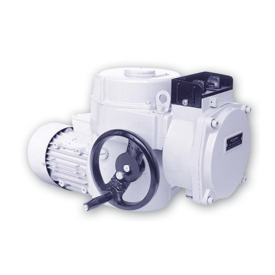
- Page 1 Elect ric Mult i-t ur n Act uat or s Ty pe nu m bers 52 030 - 52 03 6 Ty pe nu m bers 52 030 - 52 03 2 1/10...
-
Page 3: Operating Conditions
1. APPLICATION Series MODACT MONJ, MON, MOP actuators have been specially designed for adjustment of fittings and other devices for which they are suitable due to their properties and reversing rotary motion in particular. These actuators can be usedin remote control circuits. When fitted with a current transmitter, they can be used even in automatic control circuits operating in duty S4 - 25 %;... -
Page 4: Operation Mode
3. OPERATION MODE According to ČSN EN 60 034-1, actuators can be operated in S2 load category. The operation time at +50 °C shall be 10 minutes, the mean load torque value shall be below or equal to 60 per cent of the maximum switch off moment (M v ). -
Page 5: Electric Connection
Electric connection Electric connection of the actuator can be made either on the terminal boards or with a connector. Actuator terminal board The electric actuator is equipped with a terminal board for connection to external circuits. This terminal board uses screw terminals allowing conductors with a maximum cross-section 2.5 mm to be connected. - Page 6 The individual control units are distinguished by their functions as follows: a) Torque-limit switching unit -12- b) Signalling unit -13- c) Resistance transmitter setting machanism -14- d) Resistance transmitter of 2 x 100 ohm with mechanical position indicator, or current transmitter of 4 to 20 mA without position indicator -l5-, -15a- e) Position-limit switching unit -16- f) Anti-condensation heater -17-...
- Page 7 Local control unit Local control serves for controlling the actuators from the site of their installation. It consists of two selector switches: one with positions "Remote control - Off - Local control", the other with positions "Opens - Stop - Closes". If required by the customer, the actuator can be fitted with a blinker that produces electrical pulses during output shaft rotation.
- Page 8 transmitted to the tripping lever -45- or -46-. When the torque on the output shaft of the actuator reaches the value to which the torque-limit switching unit has been adjusted, the tripping lever depresses the button of the corresponding microswitch so that the electric motor is disconnected from the mains, thus stopping the actuator. Adjusting procedure of the torque-limit switching unit To adjust a different tripping torque from that adjusted at the factory, the procedure is the following: Loosen the lock nut -44- (see Fig.3) and then the lock screw -25- (for the CLOSE direction) or -26- (for the OPEN direction).
- Page 9 Open Closed Terminal numbers on terminal board 15-16 14-15 18-19 17-18 Open Closed 21-22 20-21 24-25 23-24 Contact closed Contact open Operating diagram of position-limit and signalling switches -48- (Fig.5) is the pinion -49- (Fig.5) which is connected to the shaft -46- by an adjustable friction clutch. On this pinion, the motion required for driving the resistance or current transmitter is sensed.
- Page 10 Legend: Output Gearboax Cams K 1 – Gear shaft K 2 – Drive gear K 3 – Adjusting gear 47 – Lock screw of adjusting gear 48 – Camshaft 49 – Pinion with friction clutch Note: For the individual gear-change steps, the position of the adjusting gear for the ac- tuators, Type No.
- Page 11 Legend: 68 – Current transmitter CPT 1/A 69 – Transmitter supporting plate 70 – Lock screw 71 – Shim plate 72 – Oval washers č (-) 73 – Pair of gears r/č (+) 74 – Clearance taking–up shims Fig.8 - Wheel on transmitter - gearings (version with current position transmitter) Table for setting the working stroke of the CPT 1/A current position transmitter Type number...
- Page 12 Caution! The CPT 1/A transmitter should be connected only after the supply voltage has been checked. The transmitter outlets should not be connected to the actuator frame, neither should they be earthed, even accidentally. 1) Before the supply voltage is checked the transmitter should be disconnected from the AC mains. At the actuator terminals to which the transmitter is connected, the voltage can be best measured by a digital voltmeter withan input resistance of at least 1 Mohm.
-
Page 13: Wiring Diagram
1.2. Position “20 mA” Set the drive into the required position and press the push-button “20” until LED blinks (about 2 s). 2. Setting of sense of rotation The sense of rotation is specified by viewing from the side of the panel DCPT. 2.1. - Page 14 Parameter setting Position "4 mA“ Set the actuator to required position (usually Closed) and keep the push-button 4 depressed DCPT EHL elektronika until LED blinks. v.č. 000106 Position "20 mA“ Set the actuator to a required position (usually Open) and keep the push-button 20 depressed DCPT until LED blinks.
-
Page 15: Manual Control
8) Rotate the tripping rod -58- at an angle of 90°. As a result, the rod should shift out again. If this is not the case, turn the screw -59- or -56- by a small amount. Note: Turning the regulating screw -56- or -59- should be stopped at the instant of change-over. If the cams are in the position shown in Fig.9 before they are adjusted, or the cam has already pressed down the button of the microswitch, the following procedure is used to advantage: With the tripping rod -58- depressed and positioned, turn the adjusting screw -56- or -59- anticlockwise till the cam... -
Page 16: Operation And Maintenance
9. ADJUSTMENT OF THE ACTUATOR WITH A FITTING After placing the actuator on the fitting and checking its attachment, the following adjusting procedure should be used: 1) Bring the actuator into an intermediate position by the hand. 2) Connect the actuator to the AC mains and check the correct sense of output shaft rotation by starting the actuator midway between the dead points of the working stroke for a short time. -
Page 17: Maintenance
Actuators with oil charge Check the level of oil at least yearly and refill, if required. Oil change should be made after 500 operating hours of the actuator, but not later than after 2 years of operation. The level of oil should be as high as the filling hole. For the actuator, Grade PP 80 motor-car gearbox oil or an equivalent oil with the same properties (viscosity class 80 W, according to SAE/J306a) should be used. - Page 20 Table 2 – Basic parameters of MODACT MONJ electric actuators - supply voltage 1x230V, 50 Hz Basic outfit: 2 position-limit switches (OPEN - PO, CLOSE - PZ); 2 torque-limit switches (OPEN - MO, CLOSE - MZ), 1 electric motor (brake motor upon special request); 2 anti-condensation heaters Adjusting Torque...
- Page 21 Table 3 – MODACT MON, MOP, MONJ electric actuators – designes, attachment, electric wiring Elektrische Drehantriebe MODACT MO und MODACT Control MO - Ausführung Type No ....................5 2 0 3 X 6 th position Design Attachment Bushings Connector Group A Group B1 Group C Groupr D...
- Page 27 Wiring diagrams of MODACT MONJ, MON, MOP actuators Legend: SQ1 (MO) – OPEN torque–limit switch – OPEN/CLOSE switch SQ2 (MZ) – CLOSE torque-limit switch BQ1,BQ2 – potentiometer 1x 100 ohm (V1, V2) SQ3 (PO) – OPEN position-limit switch CPT1 – CPT 1/A current position transmitter SQ5 (PZ) –...
- Page 28 Example of one-phase electric motor control (MODACT MONJ actuators) contactor contactor terminal board open close of electric motor Example of wiring power circuits for controlling a single-phase electric for selecting both directions of rotation. Control circuits are not a part of the actuator. Connector...
- Page 29 Wiring diagram of MODACT MONJ electric actuators – terminal board P0937-E DCPT DCPZ 1-phase motor open CPT1 close Outlet Control voltage position Wiring diagram of MODACT MON, MOP electric actuators P0938-E – terminal board DCPZ DCPT 3-phase motor CPT1 open close Outlet Control voltage position...
- Page 30 Wiring diagram of MODACT MONJ electric actuators – connector P0939-E P0939-E DCPT DCPZ 1-phase motor 1f motor OTV/ZAV Z1 C C U1 Z2 U2 CPT1 (V1) (V2) (MO) (MZ) (PO) (PZ) (SO) (SZ) C NO Outlet výstup Control voltage ovládací fáze position Poloha N L1...
- Page 31 LIST OF SPARE PARTS OF MODACT MONJ, MON, MOP ACTUATORS (for 5 years of operation) Type Designation Drawing or Pcs. Application Standard No. 52 030 Sealing ring 125x3 PN 029281.2 Packing between the power 2327311049 gear box and the flange with gears Sealing ring 180x3 PN 029281.2 Gasket of terminal box cover...
- Page 32 Sealing ring 16x22 224580840 Sealing of threaded oil filling plug 405052105014 Packing (according to motor) 224642240 - 1LA708,709 Packing between the electric motor 224623470 - 1LA707 and the flange with gears Sealing ring 125x5 PN 029281.2 Packing between the control box 2327311404 and the terminal box Microswitch D 443-B8LD...
- Page 33 Sealing ring 70x2 PN 029281.2 Sealing of torque spring cover 2327311058 Packing (according to motor) 224591530 - 1LA710,711 Packing between the electric motor 224642240 - 1LA709 and the flange with gears Gasket 16x22 224580840 Gasket of threaded oil filling plug 405052105074 Sealing ring 125x5 PN 029281.2...
- Page 34 Gasket 224612480 Upper seal of sun gear 405052747714 Gasket 224612590 Packing between the flange with bearing 405052743914 and differential gearing unit Gasket 224612580 Packing between the flange 405052743514 and the flange with bearing Position transmitters 52 030 Potentiometer 2 x 100 ohm 214628652 To be mounted on control board 99556-3...
- Page 35 Development, production and services of electric actuators and switchboards. Top-quality sheet-metal processing (TRUMPF equipment), powder paint shop. SURVEY OF PRODUCED ACTUATORS KP MINI, KP MIDI Electric rotary (90°) actuators (up to 30 Nm) MODACT MOK, MOKED, MOKP Ex Electric rotary (90°) actuators for ball valves and flaps MODACT MOKA Electric rotary (90°) actuators for nuclear power stations application outside containment...
- Page 36 tel.: +420 321 785 141-9 el.: +420 321 785 141-9 ZPA Pečky, a.s. fax: +420 321 785 165 ax: +420 321 785 165 tř. 5. května 166 +420 321 785 167 +420 321 785 167 289 11 PEČKY, Czech Republic e-mail: zpa@zpa-pecky.cz e-mail: zpa@zpa-pecky.cz www.zpa-pecky.cz...
Need help?
Do you have a question about the MODACT MON 52 030 and is the answer not in the manual?
Questions and answers