
Related Manuals for ZPA Pecky, a.s. MODACT MTNED Series


Summary of Contents for ZPA Pecky, a.s. MODACT MTNED Series
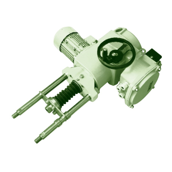
- Page 1 E l ec t r ic Li n ear ( Pu ll -ro d ) ac t u at o rs Type num b er s 52 442, 52 4 43 11/18...
- Page 2 ZPA Pečky, a.s. is certified company in accordance with ISO 9001 as amended.
-
Page 3: Table Of Contents
CONTENS 1. Application ........................2. -
Page 4: Operating Mode, Service Life Of Actuators
4) AF2 – occurrence of corrosive or polluting agents is atmospheric; presence of corrosive pollutants is significant 5) AG2 – mean mechanical strain; in normal industrial operations 6) AH2 – mean vibrations; in normal industrial operations 7) AK2 – serious risk of plant and moulds growth 8) AL2 –... -
Page 5: Technical Data
Starting thrust ≥ 1,3 . F v F stř Average mean load thrust Maximum mean tripping thrust Run time N Idle time R Cycle time Course of working cycle Service life of actuators The actuator intended for shut-off valves must be able to perform at least 10,000 operating cycles C - O - C). The actuator intended for regulating purposes must be able to perform at least 1 million cycles with operation time (during which the output shaft is moving) at least 250 hours. -
Page 6: Actuator Outfit
Self-locking The actuator is self-locking provided that the load only acts in the direction against motion of the actuator output shaft. Self-locking is ensured by a roller arrest immobilizing the electric motor rotor even in the case of manual control. In order to observe safety regulations, the actuators cannot be used for driving transportation lifting devices with possible transport of persons or for installations where persons can stand under the lifted load. -
Page 7: Electric Parameters
To extend the service life we recommend using contactless reversing unit with a minimum service life of 3 million cycles. The standard control voltage is 24V DC. It is used for output into 4 kW or 7.5 kW. The unit consists of semiconductor elements - thyristors. 6. -
Page 8: Elektronic Outfit
Legend: 1 – Three-phase asynchronous motor 2 – C ountershaft gear box 3 – P ower transmission gear 4 – H andwheel 5 – C ontrol box 6 – Control box cover 7 – T erminal box – design with terminal box 8 – Terminal box cover 9 – T erminal box – design with connector ... - Page 9 Optional outfit: Feed-back signal 4 – 20 mA, Analog module output of feed-back signal 4 – 20 mA, in version CONTROL input of control signal 0/4 – 20 mA Position indicator LED display Local control Contactors or block of contact-less control Electronic brake Main merits: Absolute scanning of position independent of backup power supply.
- Page 10 Relay SZ, SO, READY Relay 3/SZ Relay READY - It usually signalizes position closed, it can be chan- - It usually signalizes errors + warning + not remote, ged-over to any offered signalization it can be changed-over to any offered signalization Relay 4/SO - It usually signalizes position open, it can be chan- ged-over to any offered signalization...
- Page 11 Yellow Green State System without feeding lit on Everything OK – working regime (remote, local or switched off control) blinking lit on Error or warning – working regime (remote, local or switched off control) Enter or exit of Setting of parameters by means of push-buttons lit on lit on or Setting of parameters by means of PC blinking lit on blinking...
- Page 12 Overview of MENU BROWSING THROUGH MENU – The setting regime is entered by pressing and keeping depressed push-button MENU for at least 2 s; LED1 is then lit on. – Shortly press MENU to select the basic MENU – menu M1 to M8 (LED1 signalizes the menu number); by short pressing of P, O, C they are entered (LED2 signalizes particular parameter). ...
- Page 13 MENU 8 – Way of switching off in end-limit positions in 3P regulation – Shortly press P to select value TORQUE - 1x blinking of LED2, or TORQUE + PO - 2x blinking of LED2, or TORQUE + PZ - 3x blinking of LED2, TORQUE + PO + PZ - 4x blinking of LED2, And keep pressing push-button P to store the parameter to memory.
- Page 14 The recorded values are confirmed by pressing push-button START in program DMS2. For the actuator in version CONTROL, change over the actuator to remote control and, by pressing push-button START, start the autocalibration. By short starting of the motor in both directions, the actuator measures inertia and changes over to the regulating regime.
- Page 15 List of warnings and errors Name Warning Error Description Safe * Input Safe activated Control signal Value of control signal ≤ 3 mA (it applies to ranges 4 – 20/20 – 4 mA) Torque Induced torque beyond end-limit positions or disconnected torque sensor Thermal protection Thermal protection input activated Sense of rotation Reverse sense of rotation (for CONTROL only) ...
- Page 16 Example of wiring diagram of electronics DMS2 ED in version Substitution of electro-mechanical board (actuators MODACT MTNED, MTPED) E0001 E0001 Local control Místní ovládání „D“ „M“ „O“ „Z“ “R” “L” “O” “C” Position Snímač Motor Motor polohy sensor Passive open otevírej output Pasívní...
- Page 23 DMS2 Main properties of DMS2: – Complete control of the actuator run of the two- and three-position regulation or connection to the industrial bus Profibus. – Synoptic signalization of operation and service data on the character LCD display 2 x 12. –...
- Page 24 Working torque – Check and, if necessary, set the value of the working torque 50 – 100 % in program DMS2, which you change only after consultation with the armature manufacturer. Tripping in end-limit positions – Check and, if necessary, set the way of tripping in the end-limit positions:: –...
- Page 25 Autodiagnostics The table List of errors – same as for electronics DMS2 ED (page 15) Memory of number of induced errors – For all detected errors, DMS2 uses the counter of occurrence of these errors during operation of the system. – Values of the counters are stored to the EEPROM memory and are preserved even in case of the power supply fall-out. –...
- Page 26 Name Parameter value Meaning SAFE AKTIV. Active signal Safe 230 V blokuje SAFE TP SAFE Response with thermal protection activated SAFE aktivni AUTOMATICKY TP NULOVANI Zeroing of thermal protection MISTNIM OVL. VYPNUTO VAROVANI CHYBY RELE READY VAR.+CHYBY Function of Relay Ready CHYBY+NENÍ...
- Page 27 Setting actuator by means of push-buttons: – Shift the change-over switch of local control to position OFF – Keep pressing push-button STOP to enter the MENU. Using push-buttons O or Z, browse through the MENU (MENU1 – MENU27). Shortly press push-button STOP in a selected menu to enter this menu and, using push-buttons O or Z, select the parameter.
- Page 28 Terminal board of DMS2 Analog Terminal board of DMS2 Profibus...
- Page 29 DMS2 - local control and display Note: The setting program enables data to be copied from the memory of parameters of the electronics DMS2 and DMS2 ED into the computer as a file with suffix “par” (in the example in the figure the file 52 030.par is created in the directory Flash). The file can serve as a back-up for the case that it will be necessary to replace the position sensor in the given actuator and to set it in the same way as the replaced one; or it can be sent as an enclosure to e-mail to the manufacturing or service firm in solving possible problems..
- Page 35 Table 1 – MODACT MTNED, MTPED electric actuators – basic technical parameters Basic technical parameters (8 place of Type No.) Adjustment Starting Speed Stroke Weight Electric motor Type Number range thrust Revolutions basic additional Type Power I n (400 V) of tripping Type per minute 12 345 thrust [kN]...
- Page 36 7 th place of Type No. Table 4 – Connecting dimensions (Type No. 52 442) Design Design Character on 7th place Character on 7th place spacing of columns A (160 mm) spacing of columns B (160 mm) Aa1I Ba1I Aa1II Ba1II Aa1III Ba1III...
- Page 39 Dimensional sketch of MODACT MTNED 40, MTPED 40 electric actuators, Type No. 52 443.x2xxNED, 52 443.x2xxPED – design with flange – non standard – with block of terminals Local control 1x cable bushing range ø 13 - 18 mm 2x cable bushing range ø 10 - 14 mm 1x cable bushing M25x1,5 1x cable bushing diameter of cable 9-16 mm...
-
Page 40: Packing And Storing
9. PACKING AND STORING For inland freight, the actuators are unpacked. However, they should be transported by covered conveyances or in transport containers. For delivery abroad, the actuators should be packed, the type and design of package being adapted to the transport conditions and the distance of the place of destination. -
Page 41: Failures And Their Removal
Lubrication Types and quantities of lubricants are specified in table below. Lubricant included inside supplied actuators is intended for their entire service life. Lubricant does not need to be exchanged and its quantity does not need to be checked over the entire service life of actuators. Actuators with grease are identified with label stating “Filled with grease”, located on the power box on the hand wheel side. -
Page 42: Spare Parts List
List of spare parts of MODACT MTNED, MTPED actuators (for 5 years of operation) Drawing or ČSN Designation Application Standard No. 52442 Sealing ring 125x3 PN 02 9281.2 Packing between power gear box and flange with gears Sealing ring 130x3 PN 02 9281.2 Packing between control box and power gear box Sealing ring 43x35 PN 02 9280.2... - Page 43 Actuators fitted with electronics DMS2 ED Part Stock Part name Note designation item Source board DMS2.ED.Z 39620000 Position sensor multi-revolution DMS2.ED.S 39620001 Torque sensor DMS2.TORK 39620003 common for DMS2.ED and DMS2 back signal 4 – 20 mA and software Analog module DMS.ED.CPT 39620004 blocked regulator...
- Page 44 NOTES...
- Page 45 NOTES...
- Page 46 NOTES...
- Page 47 Development, production and services of electric actuators and switchboards. Top-quality sheet-metal processing (TRUMPF equipment), powder paint shop. SURVEY OF PRODUCED ACTUATORS KP MINI, KP MIDI Electric rotary (90°) actuators (up to 30 Nm) MODACT MOK, MOKED, MOKP Ex, MOKPED Ex Electric rotary (90°) actuators for ball valves and flaps MODACT MOKA Electric rotary (90°) actuators for nuclear power stations...
- Page 48 ZPA Pečky, a.s. tel.: +420 321 785 141-9 tř. 5. května 166 fax: +420 321 785 165 289 11 PEČKY, Czech Republic +420 321 785 167 www.zpa-pecky.cz e-mail: zpa@zpa-pecky.cz...
Need help?
Do you have a question about the MODACT MTNED Series and is the answer not in the manual?
Questions and answers