
Related Manuals for ZPA Pecky, a.s. Modact MOKP Ex Series


Summary of Contents for ZPA Pecky, a.s. Modact MOKP Ex Series
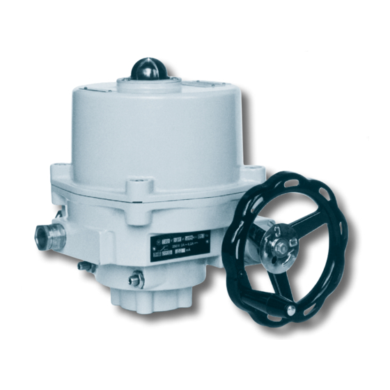
- Page 1 E lectr ic actu a to rs, ro tating , s in g le sp ee d , in n on- ex plo s iv e v e rsion, wit h c ons t ant vel oc it y o f ch ang ing- ov e r t he ou tput pa r t - c ov e rag e IP 67 Type num b ers 52 320 - 52 32 2 10/13...
- Page 3 The instructions for assembly and operation lay down basic principles of fitting, connection, adjustment, operation, maintenance and repairs of electric explosion-proof actuators. The principle assumption is that assembly, operation, maintenance, and revisions are carried out by skilled experts authorized for operation of and works on explosion-proof electric installations, and professional supervision is performed by a person professionally qualified and demonstrably instructed.
- Page 4 Marking of explosion-proof properties It includes the following marks: The electric device corresponds to the standard ČSN EN 60079-0 and associated standards for various types of protection against explosion. Marking of type of protection against explosion, explosion-proof closure, according to the standard ČSN EN 60 79-1 protection by enclosure “t”...
-
Page 5: Operating Conditions, Operating Position
OPERATING CONDITIONS, OPERATING POSITION The actuators MODACT MOKP Ex (MODACT MOKP EX Control) should withstand the effect of operating conditions and external influences, classes AC1, AD7, AE6, AF2, AG2, AH2, AK2, AL2, AM-2-2, AN2, AP3, BA4, BC3 a BE3, according to ČSN 33 2000-5-51 ed. 3. Surrounding temperature Operating temperature for the MODACT MOKP Ex is from -25 °C to +55 °C or from -50 °C to +55 °C. -
Page 6: Operation Mode, Service Life Of Actuators
OPERATION MODE, SERVICE LIFE OF ACTUATORS Operation mode The actuators can be operated with the type of loading S2 according to ČSN EN 60 034-1. The run period at temperature +50 °C is 10 minutes; the mean value of loading torque should not exceed 60 % of the value of maximum tripping torque M v . The actuators can also work in the regime S4 (interrupted run with start-up) according to ČSN EN 60 034-1. -
Page 7: Actuator Outfit
Tripping torque At the factory, the tripping torque has been adjusted as shown in Table 1, according to the customer’s requirements. If no tripping torque adjustment has been specified by the customer the maximum tripping torque is adjusted. Self-locking Actuator self-locking capacity is provided by mechanical electric motor brake, at actuator type no. 52 320 by mechanic gearbox brake. -
Page 8: Position Indicator
b) Type CPT 1A passive current transmitter. Power supply to the current loop is not a part of the actuator. Recommended feeding voltage is 18 – 28 V DC, at maximum loading resistance of the loop 500 Ω. The current loop should be earthed in one point. -
Page 9: Electric Parameters
Position regulator The position regulator built-in in the actuator enables to control position of the output shaft of the actuator and thus also the valve by the input analog signal. The control unit is microprocessor-based programmed for regulating the actuator, ascertaining and repairing error conditions, and for simple setting of regulation parameters. -
Page 10: Technical Description
Protection The actuators have external and internal protection terminal against electric shock voltage. The terminals are identified in compliance with ČSN IEC 417 (34 5550). If isn´t the actuator equipped with overcurrent protection when purchased is needed to ensure that the protection is secured externally. -
Page 11: Position Switches
set to such a position when reliable cutting out of the position switch takes place and which is still acceptable for the piping fitting. Herein, the position and moment switches are connected in series. This can only be realized in the case when a tightly closed piping fitting is not required. - Page 12 Caution! The transmitter CPT 1A must not be connected without checking the supply voltage. The transmitter outlet conductors must neither be connected to the electric actuator frame nor to the earth, not even accidentally. Before the supply voltage is checked, it is fi rst necessary to disconnect the transmitter from the supply mains. Measure the voltage on terminals of the electric actuator to which the transmitter is connected –...
- Page 13 4.1. Calibration of current 4 mA Connect the ammeter to testing terminals. Press the push-button “20”. Keep depressed the push-button to evoke the auto-repeat of current decrease. Release the push-button to make record of the present value. 4.2. Calibration of current 20 mA Connect the ammeter to testing terminals.
-
Page 14: Technical Parameters
The control and feedback signals are lead to the A/D converters of the regulator. The regulator compares the value of the control signal with the value of the feedback signal from the position transmitter. If a regulation deviation is found the regulator activates one of the output signals FO, or FZ, until the output shaft of the actuator is shifted to a position corresponding to the magnitude of the control signal. - Page 15 J1 - signal terminal board J2 - power terminal board 1 test input of logic control signal test OPEN power output "Open" 2 GND control signal - negative pole CLOSE power output "Close" 3 IN control signal - positive pole limit switch "Closed"...
- Page 16 In case the actuator is not stable, it should be immediately stopped. The best way of doing it is changing over the block of local control BMO “Local” / “0” / “Remote” to the position “0”. If the actuator is not fitted with BMO the motor can be stopped by pressing the red push-button O/I on the thermal protection.
- Page 17 (position- and/or torque-limit) of the actuator must be connected and set, and the position transmitter adjusted. If the torque-limit switches are used as the limit switches it is necessary to verify that the actuator is able to exert required tripping torque. The auto-calibration should be started in each case of changed conditions, which can influence error-free function of the regulator.
-
Page 18: Operation And Error Messages
automatically to the regime Regulation. In case that an error occurs the parameters are not stored and the actuator should be reset. After repairing the error and switching-on the feeding, the parameters should be reset and the auto-calibration repeated. Operation and error messages in the regime Auto-calibration Parameter Parameter value Note... - Page 19 Setting back-up parameters If the regulator comes into a state to be cancelled (for Switch off power supply instance, after a larger number of parameters has been changed) the system can be returned to the basic factory setting: Press SW1(L) Control signal (P1) 4 –...
- Page 20 Protection Electric motors of the actuators are fitted with a built-in automatically restoring thermal protection according to ČSN EN 600034-11. For the actuators type no. 52320 with single-phase electric motors ES 7150-2AL, ES 7130-4AL and FCJ2B52D, it is connected in series with the electric motor winding; hence, it controls the motor directly and is not con- nected to the terminal board of the actuator.
-
Page 21: Brief Description
CR-U* Compound-Filled Cable Gland - ASSEMBLY INSTRUCTIONS FOR SAFE USE Where cable gland CR-U* is used customer is obliged to follow the following instructions with sealing individual cable cores when connecting the actuator. Brief Description The Peppers CR-U* type Compound-filled cable gland is for outdoor use in the appropriate Hazardous Areas with unar- moured cable of any construction, with or without braids or screens, where the braids or screens pass trough the compound. -
Page 22: Installation Guidance
HEALTH AND SAFETY WARNING The resin used in the compound can cause eye and skin irritation. For your personal protection, wear the gloves supplied while mixing and applying. The uncured compound should not be allowed to come into contact with foodstuffs. A COMPREHENSIVE SAFETY DATA SHEET PROVIDED BY THE COMPOUNDMANUFACTURER IS AVAILABLE ON REQUEST. - Page 23 Where an earth contact is required the surface of the enclosure should be sufficiently flat and rigid. With painted enclosures a serrated star washer should be fitted to break through the paint and make a satisfactory earth contact. Once installed do not dismantle except for routine inspection. A detailed inspection should be conducted as per IEC/ EN 60079-17.
- Page 24 Instruction for Use no. N740052 – issue no.1 Non-explosive cable bushings, type lCG 623 Assembly Instructions for cable gland: ICG 623 Exd IIC/Exe II Assembly Instructions Certifi cate BASEEFA No. BAS 01 ATEX 2079X (Ex) II 2 GD IP66 CE 623 EExd I/EExe I AI 305 / Issue L - 08/06 Certifi...
- Page 25 Tape Remove surplus compound Remove Compound surplus Remove compound surplus compound With all gaps and voids fi lled, bring Replace the entry (5) over the rubber Locate and hand tighten the sub-as- the conductors back together and pot (4) ensuring that compound does sembly (1) and (2) to the entry (5).
- Page 26 EPOXY COMPOUND PREPARATION When handling this material, the gloves supplied must be worn. The epoxy compound is supplied in the form of a two part package. These should be mixed into the ratio of I: I until both colours have blended into one, without any streaks.
- Page 27 3.0. Insulating drainwireswith insulating varnish or paint 3.1. Fold back the armour I braid and bend it at right angles from the inner sheath. 3.2. Remove the foil and tape level with the inner sheath exposing the drain wires and conductor pairs. 3.3.
- Page 28 Limiting conditions: 1. Cable bushings OS and O can only be used for braided cables and firm instruments; the cable should be properly fixed to prevent its possible pulling out or twisting. 2. Operating temperature of the cable bushing is -60 °C to +80 °C. 3.
- Page 29 OPERATION AND MAINTENANCE OF ELECTRIC ACTUATORS Operation of the electric actuators results from the operating conditions and, as a rule, it is limited to giving impulses to respective functional tasks. The electric actuator can be controlled electronically in remote way as well as manually on site of their installation.
- Page 30 Table No. 1 – MODACT MOKP Ex electric actuators – basic technical parameters Type number Electric motor Adjusting Tripping Weight Basic Complem. time torgue range Type Power Voltage Current Capacity Type 1.min -1 s/90 ° μF 1 2 3 4 5 6 7 8 9 x x 1 x ES 7150-2AL...
- Page 31 The type number indikates Place 6: stroke 90° stroke 60° stroke 120° stroke 160° Using transmitter with resistance transmitter 2x100 Ω with CPT 4-20 mA without built-in feeding source without transmitter with DCPT 4-20 mA with built-in feeding source Place 7: version without built-in regulator of position and without BMO (block of local control) version with built-in regulator of position and without BMO (Note 1) version without built-in regulator of position and with BMO...
- Page 32 Table 2 – Way of connecting MODACT MOKP Ex electric actuators – specifying of the 9th place in type number Marking of the Square size Structural design Flange size Connection Square position 9th position s [mm] of output in the type number Type number 52 320 keyway collar...
- Page 33 Dimensional sketch of MODACT MOKP 100 Ex and 250 Ex electric actuators 2x Cable bushing M20 x 1.5 2 x kabelový vstup M20x1,5 for local control pro místní ovládání Block of local control (BMO) Not applied for version with BMO Odpadá...
- Page 34 Dimensional sketch of MODACT MOKP 600 Ex electric actuators Cable bushing M20x1,5 Block of local control (BMO) 2x cable bushing M20x1,5 for version with BMO Not applied for version with BMO 2x cable bushing M25x1,5 Threaded holes for cable entries are marked M20x1,5 or M25x1,5 in accordance with article 13 of ČSN EN 60079-1. These entries are sealed by plugs M20x1,5 or M25x1,5.
- Page 35 Fig. 1: Control plate (Type No. 52 321) Legend: 1 – position unit 2 – position transmitter 3 – moment unit 4 – terminal board 5 – electric motor 6 – internal protective connector 7 – drive wheel (or segment) 8 –...
- Page 36 Fig. 1a: Control plate (Type No. 52 322) Legend: 1 – position unit 2 – position transmitter 3 – moment unit 4 – terminal board 5 – electric motor 6 – internal protective connector 7 – drive wheel (or segment) 8 –...
- Page 37 Fig. 2: Control plate (Type No. 52 320) Legend: 1 – position unit 2 – position transmitter 3 – moment unit 4 – terminal board 5 – electric motor 6 – internal protective connector 7 – drive wheel (or segment) 8 –...
- Page 38 Fig 3: Moment switches Legend: 1 – cam of switch MO 2 – cam of switch MZ 3 – moment switch MO 4 – moment switch MZ 5 – releasing screw of cam switch MZ 6 – releasing screw of cam switch MO...
- Page 39 Connecting dimensions of MODACT MOKP Ex electric actuators – connecting with square ø d5 ø d2 ø d1 “Z” (“C”) “Z” (“C”) The position of the square hole in end position of electric actuator. The position “Opened” is to the left of the position “Closed”...
- Page 40 Connecting dimensions of MODACT MOKP Ex electric actuators – connecting with keyway ø ø ø ø “Z” (“C”) The position of groove for keyway according to ISO 5211 and DIN 3337 is in the position “Closed”. The position “Opened” is to the left of the position “O”...
- Page 41 Wiring diagrams of MODACT MOKP Ex electric actuators Legend: M1 ~, TH – electric motor, single-phase, with thermal protection SQ1 (MO) – moment switch for direction “opens” – motor capacitor SQ2 (MZ) – moment switch for direction “closes” M3~, TH –...
- Page 42 Wiring diagrams of MODACT MOKP Ex electric actuators, Type No. 52 320 - 52 322 P0816 P0817 control voltage P0818-E Note: The position and signalling switches can work as a single-circuit type. State of contacts in the scheme is valid for the intermediate position.
- Page 43 P0819 P0820 switched control voltage contactors P0821-E Note: The position and signalling switches can work as a single-circuit type. State of contacts in the scheme is valid for the intermediate position. In the version with the current transmitter the user shall ensure connection of the double-wire circuit of the current transmitter to electric earth of the linked-up regulator, computer, etc.
- Page 44 Wiring diagram of MODACT MOKP Ex Control electric actuators, Type No. 52 320 - 52 322 P0822-EZ J2.E J2.D J2.C J2.B DCPZ J2.A O / C L / R +U -U DCPT J2.H Ureg J2.G -U +U J2.F Uovl J1.1 TEST J1.9 +24V...
- Page 45 Wiring diagram of MODACT MOKP Ex Control electric actuators, Type No. 52 320 - 52 322 Motors 60, 90W Motory 60, 90W č P0823-EZ č J2.E J2.D J2.C J2.B DCPZ J2.A +U -U DCPT J2.H Ureg J2.G -U +U J2.F Uovl J1.1 TEST...
- Page 46 Spare parts for MOKP Ex Name: Actuator type no.: Using, note: “O” – ring 180x3 52 320 Between cover and box of power part “O” – ring 210x3 52 321 Between cover and box of power part “O” – ring 250x3 52 322 Between cover and box of power part Micro-switch CHERRY DB1G-A1LC...
- Page 47 Development, production and services of electric actuators and switchboards. Top-quality sheet-metal processing (TRUMPF equipment), powder paint shop. SURVEY OF PRODUCED ACTUATORS KP MINI, KP MIDI Electric rotary (90°) actuators (up to 30 Nm) MODACT MOK, MOKED, MOKP Ex, MOKPED Ex Electric rotary (90°) actuators for ball valves and flaps MODACT MOKA Electric rotary (90°) actuators for nuclear power stations...
- Page 48 ZPA Pečky, a.s. tel.: +420 321 785 141-9 tř. 5. května 166 fax: +420 321 785 165 289 11 PEČKY, Czech Republic +420 321 785 167 www.zpa-pecky.cz e-mail: zpa@zpa-pecky.cz...
Need help?
Do you have a question about the Modact MOKP Ex Series and is the answer not in the manual?
Questions and answers