Table of Contents
Advertisement
Quick Links
MODACT MOK
63
MOK
125
MOK
250
MOK
500
MOK 1000
MOK 1000
MOK 1000
MODACT MOK CONTROL
MODACT MOK CONTROL
MODACT MOK CONTROL
t.n. 52 325
t.n. 52 326
t.n. 52 327
t.n. 52 328
t.n. 52 329
t.n. 52 329
t.n. 52 329
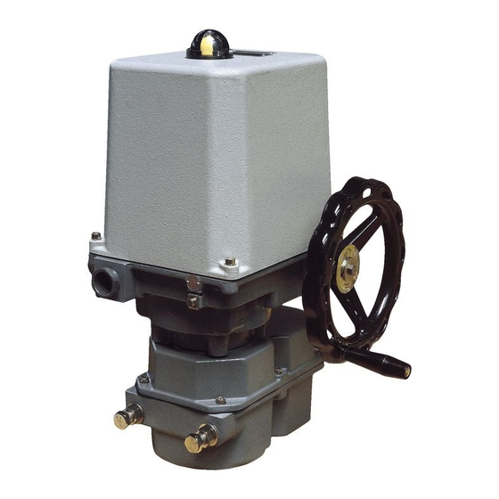
Elect ric Pa r t-tu r n (90° ) Actu ato rs
for Ball a n d F lap Valve s
Type Num b ers 52 325 - 52 32 9
10/18
Advertisement
Table of Contents

Related Manuals for ZPA Pecky, a.s. MODACT MOK 125


Summary of Contents for ZPA Pecky, a.s. MODACT MOK 125
- Page 1 MODACT MOK t.n. 52 325 t.n. 52 326 t.n. 52 327 t.n. 52 328 MOK 1000 MOK 1000 MOK 1000 t.n. 52 329 t.n. 52 329 t.n. 52 329 MODACT MOK CONTROL MODACT MOK CONTROL MODACT MOK CONTROL Elect ric Pa r t-tu r n (90° ) Actu ato rs for Ball a n d F lap Valve s Type Num b ers 52 325 - 52 32 9 10/18...
- Page 2 ZPA Pečky, a.s. is certified company in accordance with ISO 90001 as amended.
-
Page 3: Table Of Contents
CONTENS 1. Application ........................2. -
Page 4: Operation Mode, Service Life Of Actuators
4) AF2 – occurrence of corrosive or polluting substances from atmosphere. Presence of corrosive polluting substances is significant. 5) AG2 – medium mechanical stress by impacts – common industrial processes 6) AH2 – medium mechanical stress by vibrations – common industrial processes 7) AK2 –... -
Page 5: Technical Data
starting torque ≥ 1,3 . M v M stř mean value of loading torque maximum value of tripping torque Run time N Idle time R Cycle time Course of working cycle Service life of actuators The actuator intended for shut-off valves must be able to perform at least 10,000 operating cycles (C - O - C). The actuator intended for regulating purposes must be able to perform at least 1 million cycles with operation time (during which the output shaft is moving) at least 250 hours. -
Page 6: Actuator Outfit
handwheel is rotated clockwise the output shaft of the actuator also rotates clockwise (when looking at the shaft towards the control box). On condition that the valve nut is provided with left-hand thread, the actuator closes the valve. Torque-limit switches in the actuator are set and work when the actuator is under voltage. When using the manual control, ie. -
Page 7: Electric Parameters
Technical parameters of DCPT: Scanning of position contact-less magneto-resistant Working stroke adjustable 60° – 340° Non-linearity max. ±1 % 0 – 500 Ω Loading resistance Output signal 4 – 20 mA or 20 – 4 mA Power supply 15 – 28 V DC, < 42 mA Working temperature -25 °C to +70 °C Dimensions... -
Page 8: Technical Description
Electric strength of electric circuits isolation Circuit of resistance transmitter 500 V, 50 Hz Circuit of current transmitter 50 V DC Circuits of microswitches and anti-condensation heater 1 500 V, 50 Hz Electric motor Un = 1 x 230 V 1 500 V, 50 Hz Un = 3 x 230/400 V 1 800 V, 50 Hz... -
Page 9: Adjustment Of The Actuator
– Control section which is identical for all MODACT MOK actuators, Types MOK 125 to MOK 1000 type no., with the only exception that, it differs in angular displacement of units on the base plate. In the actuator, Type No. 52 325, the unit of position-limit signalling switches is arranged as shown in Fig 1. - Page 10 b) Position-limit switches Position-limit switches PO, PZ switch off an electric actuator when the output shaft reaches the position for which they are set. Signalling-limit switches SO, SZ signalise the position of electric actuator output shaft. The setting of position-limit switches is carried out by positioning the output shaft into the position in whichthe set switch should switch off.
- Page 11 Caution! The transmitter CPT 1Az must not be connected without checking the supply voltage. The transmitter outlet conductors must neither be connected to the electric actuator frame nor to the earth, not even accidentally. Before the supply voltage is checked, it is first necessary to disconnect the transmitter from the supply mains. Measure the voltage on terminals of the electric actuator to which the transmitter is connected –...
-
Page 12: Position Regulator Zp2.Re Version 4
4. Calibration of currents 4 mA and 20 mA. On switching-on the power supply, keep the push-buttons “4” and “20” depressed and release them after a single blink of LED. In this way the option menu 4.1 Calibration of current 4 mA is entered. 4.1. - Page 13 The microcomputer includes: – A/D converters for input and feedback signals processing. – Memory of parameters. – Power supply source with mains transformer. – Output relays for controlling the actuator (they switch on the electric motor or power switches). – Input circuits for connection of end micro-switches and contact of thermal relay. –...
- Page 14 REGULATOR ZP2.xx Layout of indicator LEDs, push-buttons, terminals and connectors value selection menu, of parameter, of menu, setting state of control error control/setting of parameter error code connector marking of version of of connecting to PC control program green open close OPEN CLOSE...
-
Page 15: Technical Parameters Of Actuator
Attention! Even after this switching off the actuator circuits are under voltage. Before any works on the actuator, e.g. change of phase sequence in the actuator terminal board, the mains voltage should be disconnected. Note: In the auto-calibration regime the regulators ZP2 version 4 perform testing of the sense of rotation and report the incorrect direction as an error. - Page 16 Before setting the parameters, limit switches of the actuator must be connected and adjusted and the position transmitter must be set. If moment switches are used as limit switches it is necessary to ensure that the actuator or the valve can produce required tripping moment. The parameters of the regulator cannot be set as long as the actuator shaft is in one of its extreme positions and if it is switched off by the limit switch;...
- Page 17 By the regulation “to position” the actuator shaft is set to the position in which the input and feedback signals are equal. The regulation “to moment” means that, in setting the input signal close to limiting positions - for the signal 4 – 20 mA this is up to the value of about 4.2 mA and above 19.8 mA (these values are fix set and cannot be changed), the actuator shaft is not stopped when the input and feedback signals are equal but it goes on moving until it is stopped by action of the particular limit switch.
-
Page 18: Installation And Putting Into Operation
Important warning: This procedure can be used in setting the parameters the setting of which cannot be changed without a connected computer (e.g. voltage level on TP input in which the regulator changes over into an error state - this can cause problems in the actuators MODACT MOK 500 and 1000 where it is necessary to set an opposite active level than the one set by the regulator manufacturer). -
Page 19: Attendance And Maintenance
At the end of the adjusting procedure, subject the actuator to a functional check by means of the control circuit, making sure particularly that the actuator starts correctly and is not “alive” after tripping of the respective microswitch. If this is not the case, the actuator should be immediately disconnected from the mains to avoid a damage to the electric motor and to find out the failure. -
Page 20: Tables
Table 1 – MODACT MOK (Control) electric actuators – basic technical parameters Type number Electric motor Adjusting Tripping Weight Type time torque basic complem. Output Speed Voltage Current [kg] Type [s/90°] [Nm] 1 2 3 4 5 6 7 8 9 [1.min x x 1 x 16 – 32... - Page 21 Table 2 – MODACT MOK (Control) – way of mechanical connection (specification of 9 place of type number) Square size Flange size Connection Square position Marking on the 9 place of type number s [mm] Type Number 52 325 keyway Ø 22 square basic keyway Ø...
-
Page 22: Dimensional Sketch Of Electric Actuators Mok
Addition to table 2 – MODACT MOK electric actuators with lever adapter – mechanical connection (designation of the 9th place of the type number) Marking of the 9th position Structural design Flange size Connection Square size s [mm] Square position in the type number of output Type number 52 325... - Page 23 Lever adapter with Type No. 52325 actuator M2:1 (pohled na základní desku) (view of the base plate)
- Page 24 Lever adapter with Type No. 52326 actuator M2:1 (pohled na základní desku) (view of the base plate) Note: Other dimensions are listed in the dimension table.
- Page 25 Dimensional sketch of MODACT MOK electric actuators Local control M20x1,5 (1 0 – 14 mm) Cable bushings: Local MOK 63 1x M20x1,5 (10 – 14 mm) control 1x M25x1,5 (13 – 18 mm) MOK 125, 250 2x M25x1,5 (13 – 18 mm) MOK 500, 1000 1x M25x1,5 (13 –...
- Page 26 Connection dimensions of MODACT MOK actuators – for valves and control devices with spindles that are provided with a tight-fit keyway Position of the keyway, according to ISO 5211 and DIN 3337 (The groove is in the CLOSE position whereas the OPEN posi- tion is on the left side when viewing the local position indicator) ø...
-
Page 27: Wiring Diagrams
Wiring diagrams of MODACT MOK electric actuators Legend: – Three-phase motor SQ1 (MO) – OPEN torque-limit switch – Electromagnetic brake – Resistance transmitter 1x 100 Ω SQ2 (MZ) – CLOSE torque-limit switch SQ3 (PO) – OPEN position-limit switch CPT 1 –... - Page 28 Wiring diagram of MODACT MOK 63 electric actuators – with a one-phase motor – with the current transmitter without built-in power supply or without transmitter, with local control or without local control P1023 – with the current transmitter with built-in power supply, with local control or without local control P1024...
- Page 29 Wiring diagram of MODACT MOK 63 electric actuators – with three-phase electric motor – with current transmitter and built-in power supply, with local control or without local control Control phase P-0872-E – with the resistance transmitter, without local control or with local control P0762V1 Control phase...
- Page 30 Wiring diagrams of MODACT MOK 125 – 1000 electric actuators – with a one-phase motor – with the resistance transmitter and local control or without local control P1025 – with a three-phase motor – with the resistance transmitter and local control or without local control...
- Page 31 Wiring diagrams of MODACT MOK 125 – 1000 electric actuators – with a one-phase motor – with the current transmitter without built-in power supply or without transmitter, with local control or without local control P1027 – with the current transmitter with built-in power supply,...
- Page 32 Wiring diagrams of MODACT MOK 125 – 1000 electric actuators – with three-phase electric motor – with the current transmitter without built-in power supply or without transmitter, with local control or without local control P1029 – with the current transmitter with built-in power supply,...
- Page 33 70 – 71 interconnect mA propojit mA, max. 24 V or with jumper nebo propojkou Wiring diagram of MODACT MOK 125 – 1000 Control electric actuators – with the one-phase motor and position regulator P-0780-EZ P0780-EZ J2.E J2.D J2.C DCPZ J2.B...
- Page 34 MOK63 3f motor Wiring diagram of MODACT MOK 63 Control electric actuators – with the three-phase motor and position regulator P-0920-EZ P0920-EZ J2.E J2.D J2.C J2.B DCPZ J2.A OTV/ZAV +U -U DCPT J2.F Uovl J2.G J2.H -U +U Ureg Finder J1.1 56.34 TEST...
-
Page 35: Wiring Diagrams
The TEST signal can be activated by an external make contact. This signal need not be connected. From the terminals 25 and 26 (for MODACT MOK 125, 250, 500 and 1000) or 77 and 80 (for MODACT MOK 63), a failure signal can be brought out. This signal is galvanically separated from the regulator circuits. -
Page 36: Spare Parts
Spare parts Designation Application Microswitch DB1G - A1LC MO, MZ, PO, PZ, SO, SZ available from ZPA Pečky a.s. Packing 224648300 Packing between the control section cover and the power unit box for actuators, Type Nos 52 325 Packing 224648301 Packing between the control section cover and the power unit box for actuators, Type Nos 52 326, 52 327 Packing... - Page 37 NOTE...
- Page 38 NOTE...
- Page 39 Development, production and services of electric actuators and switchboards. Top-quality sheet-metal processing (TRUMPF equipment), powder paint shop. SURVEY OF PRODUCED ACTUATORS KP MINI, KP MIDI Electric rotary (90°) actuators (up to 30 Nm) MODACT MOK, MOKED, MOKP Ex, MOKPED Ex Electric rotary (90°) actuators for ball valves and flaps MODACT MOKA Electric rotary (90°) actuators for nuclear power stations...
- Page 40 ZPA Pečky, a.s. tel.: +420 321 785 141-9 tř. 5. května 166 fax: +420 321 785 165 289 11 PEČKY, Czech Republic +420 321 785 167 www.zpa-pecky.cz e-mail: zpa@zpa-pecky.cz...
Need help?
Do you have a question about the MODACT MOK 125 and is the answer not in the manual?
Questions and answers