Advertisement
Quick Links
DRW171185AA
DIGITAL PRESSURE SENSOR(Pneumatic type)
PSAN SERIES
I N S T R U C T I O N M A N U A L
Thank you very much for selecting Autonics products.
For your safety, please read the following before using.
Safety Considerations
※Please keep these instructions and review them before using this unit.
※Please observe the cautions that follow;
Warning
Serious injury may result if instructions are not followed.
Caution
Product may be damaged, or injury may result if instructions are not followed.
※The following is an explanation of the symbols used in the operation manual.
Caution: Injury or danger may occur under special conditions.
Warning
1. Fail-safe device must be installed when using the unit with machinery that may cause serious injury or
substantial economic loss. (e.g. nuclear power control, medical equipment, ships, vehicles, railways,
aircraft, combustion apparatus, safety equipment, crime/disaster prevention devices, etc.)
Failure to follow this instruction may result in fire, personal injury, or economic loss.
2. Install on a device panel or to a pressure port directrly to use.
Failure to follow this instruction may result in fire.
3. Do not connect, repair, or inspect the unit while connected to a power source.
Failure to follow this instruction may result in fire.
4. Check 'Connections' before wiring.
Failure to follow this instruction may result in fire.
5. Do not disassemble or modify the unit.
Failure to follow this instruction may result in fire.
Caution
1. Use the unit within the rated specifications.
Failure to follow this instruction may result in fire or product damage.
2. Use dry cloth to clean the unit, and do not use water or organic solvent.
Failure to follow this instruction may result in fire.
3. This product is designed to detect the pressure of noncorrosive gas. Do not use for corrosive gas.
Failure to follow this instruction may result in product damage.
4. Do not use the unit in the place where flammable/explosive/corrosive gas, humidity, direct sunlight,
radiant heat, vibration, impact, or salinity may be present.
Failure to follow this instruction may result in fire or explosion.
5. Keep metal chip, dust, and wire residue from flowing into the unit.
Failure to follow this instruction may result in fire or product damage.
Dimensions
30.7
30.7
22.8
7.9
30
20
2-M3 Tap
22.8 7.9 8
※A
●Accessory
. Bracket A
. Bracket B
Ø4.2
25
20
3-Ø3.2
30
14
20
3-Ø3.2
14
20
13
30
Ø4.2
35
22
●Sold separately
. Front cover(PSO-P01)
. Panel bracket(PSO-B02/B03)
40
5.7
40
10
1
30
● Panel cut-out
36
+0.5
0
(panel thickness: 0.8 to 3.5mm)
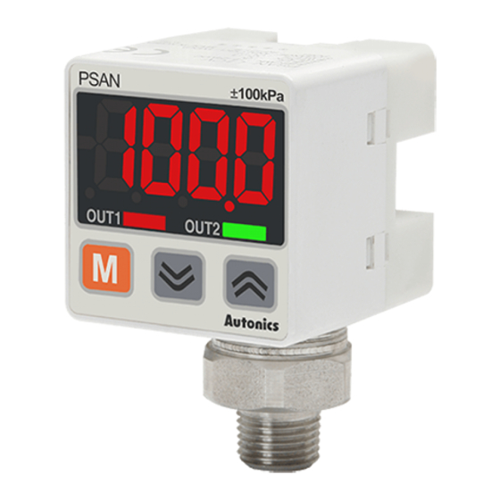
Unit Descriptions
1. Range of rating pressure: It is possible to change the pressure unit in Pressure
1
sensor. Please use different unit as label for your application.
2. 4digit LED display(Red): Used to indicate measured pressure value, setting
2
value and error message.
3. Output1 indicator(Red): Output 1 is ON, LED will be ON.
3
4
4. Output2 indicator(Green): Output 2 is ON, LED will be ON.
5.
key: Used to enter into Preset/Parameter setting mode and to save Setting
5
mode.
6.
,
key: Used to set parameter and preset, peak value check mode, function
setting or output operation mode.
6
+
key: Used for zero point adjustment function by pressing
over 1 sec. simultaneously in RUN mode.
Functions
Pressure unit change
PSAN-V01C(P) and PSAN-C01C(P) has 7 kinds of pressure unit, PSAN-01C(P) and PSAN-1C(P) has 5 kinds
of pressure unit. Please select the proper unit for application.
• PSAN-V01C(P), PSAN-C01C(P) : kPa, kgf/cm
2
, bar, psi, mmHg, inHg, mmH
2
• PSAN-01C(P), PSAN-1C(P) : MPa, kPa, kgf/cm
, bar, psi
※ When using mmH
O unit, please multiply display value by 100.
2
Output mode change
There are 5 kinds of control output mode in order to realize the various pressure detection.
• Hysteresis mode [ HYsM] : When needed to change hysteresis for detecting pressure.
• Window comparison output mode [ WIN] : When needed to detect pressure in certain area.
• Hysteresis - Window comparison output mode [ HY-W] : When both hysteresis mode and window comparison
output mode are required.
• Automatic sensitivity setting mode [ AUTO] : When needed to set detection sensitivity automatically at proper
position.
• Forced output control mode [ fOUT] : When needed to display pressure with remaining comparison output
OFF regardless of setting value.
Control output change
Type of control output for Out1 and Out2 can be able to set Normally Open and Normally Closed.
※ Note that Normally Open and Normally Closed provide opposite output.
Response time change(chattering prevention)
It can prevent chattering of control output by changing response time.
It is able to set 5kinds of response time(2.5ms, 5ms, 100ms, 500ms, 1000ms) and if the response time is
getting longer, the detection will be more stable by increasing the number of digital filter.
Analog output scale setting and Hold/Auto Shift setting
• Analog voltage output scale setting: The scale function for analog output voltage (1-5VDC) is not fixed to the
rated pressure range. It can be changed for User's application. Analog output is 1-5VDC within the pressure
range from the pressure point[A-1V] for 1VDC to the pressure point [A-5V] for 5VDC.
• Analog current output scale setting: The scale for analog output Current (DC4-20mA) is not fixed to the rated
pressure range. It can be changed for User's application. Analog output is 4-20mA within the pressure range
from the pressure point [A-04] for 4mA to the pressure point [A-20] for 20mA.
• Hold/Auto Shift input setting
- Hold function: A function to hold PV and Control output while signal is input.
- Auto Shift function: A function to compensate the setting value for changed value of reference pressure as
threshold level if reference pressure of the device changes.
Key lock
The key lock function prevents key operations so that conditions set in each mode. [preset/parameter mode are
not inadvertently changed. There are 2 kinds of key lock functions available.
• LOC1: All keys are locked; therefore it is not available to change parameter settings, preset value, zero
adjustment, High/Low peak check and SH.IN data initialization. (Lock setting change is available)
• LOC2: Partially locked status; therefore it is not available to change parameter settings only(Lock setting
change is available). Other settings are still available.
• OFF: All of the setting is available, all keys are unlocked.
Zero point adjustment
The zero point adjustment function forcibly sets the pressure value to "Zero" when the pressure port is opened
to atmospheric pressure. When the zero adjustment is applied, analog output [Voltage or Current] is changed
by this function.(Press
+
keys over 1 sec. in RUN mode.)
High Peak / Low Peak Hold Function
This function is to diagnosis malfunction of the system caused by parasitic pressure or to check through
memorizing the max./min. pressure occurred from the system.
Error
Display
Description
ERR1
When external pressure is input while adjusting zero point. Try again after removing external pressure.
ERR2
When overload is applied on control output
When setting condition is not met in Auto sensitivity
ERR3
setting mode.
When applied pressure exceeds Low-limit of display
LLLL
pressure range.
When applied pressure exceeds High-limit of display
HHHH
pressure range.
-HH-, -LL-,
Auto shift correction error.
-HL-
※ The above specifications are subject to change and some models may be discontinued without notice.
※ Be sure to follow cautions written in the instruction manual and the technical descriptions
(catalog, homepage).
Specifications
Pressure type
Voltage output
Current output
Hold/Auto shift input PSAN-V01C(P)H-
Rated pressure range
Display pressure range 5.0 to -101.3kPa
Min.display unit
Max. pressure range
Applied fluid
Power supply
Current consumption
Control output
※2
Hysteresis
Repeat error
Response time
Short circuit protection Built-in
Voltage output
Current output
Display method
Resolution
Pressure unit
MPa
kPa
kgf/cm
2
bar
psi
mmHg
inHg
mmH₂O
Display accuracy
Dielectric strength
Insulation resistance
Vibration
Ambient temp.
Environ-
ment
Ambient humi.
Protection
Material
Cable
Approval
※
Weight
5
※1: (P) is PNP output type, of model name is as pressure port.
Rc1/8: PT1/8"model(standard), NPT1/8: NPT1/8"model(option),
R1/8: PT1/8"model(Option)
※2: In hysteresis output mode, detection difference is variable.
※3: It is allowed to select one analog output type only.
(unit:mm)
※A
※
: Resolution(1000/2000) of min. Display interval is automatically
4
selected depend on pressure units.
PT1/8"model
※
: This weight is with packaging and the weight in parentheses is
(standard)
5
8
PT1/8"
only unit weight.
NPT1/8"model
Output Operation Mode
※ PSAN series has 5 kinds of output operation mode, please use proper output operation mode in
Inside
accordance with detection.
M5 Tap
Hysteresis mode[ HYS.M]
It is able to set certain value for pressure detection
level[ST1, ST2] and hysteresis[HYS1, HYS2].
. Pressure unit label
Pressure
ST2
HYS2
ST1
HYS1
. Connector cable(PSO-C01, 2m)
OUT1 N.O.
ST1/ HYS1
. M5 Gender(PSO-Z01)
OUT1 N.C.
ST1/ HYS1
OUT2 N.O.
ST2/ HYS2
25.8
OUT2 N.C.
ST2/ HYS2
20
3
Hysteresis-window comparison output mode[ HY-W]
①It is available to set hysteresis mode[ ST1, HYS1]
and window comparison output mode when both
hysteresis mode and window comparison output
mode[LOW, HIGH] are necessary.
②Detection hysteresis is fixed to min. display range.
Pressure
※1
HIGH
※1
LOW
ST1
HYS1
OUT1 N.O.
ST1/ HYS1
OUT1 N.C.
ST1/ HYS1
OUT2 N.O.
LOW/ HIGH
OUT2 N.C.
LOW/ HIGH
Forced output control mode[ fOUT]
①Used to display pressure with forcibly holding comparing output OFF regardless of setting value.
②In parameter setting, if output operation mode setting[ OUtN] is changed to [fOUT] , forced output control
mode is operated.
③OUT1, 2 can be ON/OFF manually by pressing
+
keys
RUN mode
fOUT
RUN mode
O
2
Input/Output Circuit and Diagram
Analog output type (Voltage output PSAN-
● NPN open collector output type
Over current
protection
circuit
Over current
protection
circuit
1kΩ
※
: For voltage output type only.
Hold / Auto Shift input type (PSAN-
● NPN open collector output type
Over current
protection
circuit
Over current
protection
circuit
※ If short-circuit the control output terminal or supply current over the rated specification, normal control
signal is not output due to the output short over current protection circuit
Installation
1.Pressure port is divided as basic and option specification.
Therefore, be sure that to use commercially available one
touch fitting. (Standard: Rc1/8", Option: NPT1/8", R1/8")
2.Please connect it by using spanner(12 mm ) at the
metal part in order not to overload on the body when
connecting one touch fitting.
3.Two different fixing brackets are provided for PSAN
model. Select proper one with considering your
Countermeasures
application environments.
4.At first, please unscrew hexagon wrench bolt and
assemble the bracket on this unit by fixing hexagon
Remove overload.
the wrenchbolt. In this case, tightening torque of
hexagon wrench should be max. 3N . m. It may cause
Check setting conditions and set proper
mechanical problems.
setting values.
Spring washer
Apply pressure within display pressure
range.
Set the corrected setting value within
setting pressure range.
Bracket A
6. Do not pull the cable with a tensile strength of 30N or over.
Gauge pressure
Negative pressure
Standard pressure
PSAN-V01C(P)V-
PSAN-01C(P)V-
PSAN-1C(P)V-
PSAN-V01C(P)A-
PSAN-01C(P)A-
PSAN-1C(P)A-
PSAN-01C(P)H-
PSAN-1C(P)H-
0.0 to -101.3kPa
0.0 to 100.0kPa
0 to 1,000kPa
-5.0 to 110.0kPa
-101.3 to 1,100kPa
0.1kPa
0.1kPa
1kPa
2 times of rated
2 times of rated
1.5 times of rated
pressure
pressure
pressure
Air, Non-corrosive gas
12-24VDCᜡ ±10%(ripple P-P:Max. 10%)
Max. 50mA(Analog Current Output type Max 75mA)
NPN or PNP open collector output
• Load voltage: Max. 30VDCᜡ • Load current: Max. 100mA
• Residual voltage - NPN: Max. 1VDCᜡ, PNP: Max. 2VDC
Min. display range
±0.2%F.S. ± Min. display range
Selectable 2.5ms, 5ms, 100ms, 500ms, 1000ms
• Output voltage: 1-5VDCᜡ ±2% F.S. • Linear: Max. ±1% F.S. • Output impedance: 1kΩ
• Zero point: Max. 1VDCᜡ ±2% F.S. • Span: Max. 4VDCᜡ ±2% F.S. • Response time: 50ms
• Resolution: Automatically changed to 1/1000 or 1/2000 by pressure unit
• Output current: DC4-20mA ±2% • Linear: Max. ±1% F.S.
• Zero-point: Max. DC4mA ±2% F.S. • Span: Max. DC16mA ±2% F.S. • Response time:70ms
• Resolution: Automatically changed to 1/1000 or 1/2000 by pressure unit
7segment LED Display
1000
2000
1000
2000
1000
2000
-
-
0.001
-
0.001
-
0.1
-
0.1
-
1
-
0.001
-
0.001
-
0.01
-
0.001
-
0.001
-
0.01
-
-
0.01
-
0.01
-
0.1
-
0.4
-
0.02
0.1
-
0℃ to 50℃ : Max. ±0.5% F.S., -10 to 0℃ : Max. ±1% F.S.
1000VAC 50/60Hz for 1 minute
Over 50MΩ(at 500VDC megger)
1.5mm amplitude at frequency of 10 to 55Hz(for 1 min.) in each of X, Y, Z direction for 2 hours
-10 to 50℃, storage : -20 to 60℃
30 to 80%RH, storage :30 to 80%RH
IP40(IEC specification)
Front case: PC, Rear case: PC, Pressure port: Nickel Plated Brass
Connector cable (Ø4mm, 5-wire, Length: 2m)
(AWG24, Core diameter : 0.08mm, Number of cores : 40, Insulator out diameter: Ø1mm)
Approx. 165g(approx. 80g)
※F.S.: Rated pressure.
※There may be ±1digit error in hysteresis
by pressure unit calculation error.
※For using mmH
O unit, multiply display
2
value by 100.
※Environment resistance is rated at no
freezing or condensation.
Window comparison output mode[ WIN]
①It is able to set the range for high[ HI-1, HI-2]/
low[LO-1, LO-2]limit of pressure detection level when
it is required to detect pressure at a certain range.
②Detection hysteresis is fixed to min. display range.
Pressure
※1
HI-2
※1
LO-2
※1
HI-1
※1
LO-1
Time
OUT1 N.O.
LO-1/ HI-1
Time
OUT1 N.C.
LO-1/ HI-1
Time
OUT2 N.O.
LO-2/ HI-2
Time
OUT2 N.C.
LO-2/ HI-2
Time
Automatic sensitivity setting mode[ AUTO]
①This function is to set pressure detection level
to the proper position automatically. It is set by
applied pressure from two positions[ST1, ST2].
②Detection hysteresis is fixed to min. display range.
③The pressure detection level[ SET] is shown in
the following calculation.
Pressure
※ 1: Min. display range
※1
ST2
SET=(ST1+ST2)/2
SET
※1
ST1
※1
Time
OUT1 N.O.
SET
Time
OUT1 N.C.
SET
Time
OUT2 N.O.
ST1/ ST2
Time
OUT2 N.C.
ST1/ ST2
Time
,
key While the forced output control mode is applied.
RUN mode
Forced output control mode
operation status
Current pressure
ON
8#1
OFF
OUT1
Flashing
in turn
ON
OFF
OUT2
□□□□
□
□□□□
V-
, Current output PSAN-
● PNP open collector output type
(Brown)+V
(Brown)+V
Over current
Load
(Black)OUT1
protection
circuit
(Black)OUT1
Load
Over current
(White)OUT2
protection
circuit
12-24VDC
(White)OUT2
(Orange)
(Orange)
Analog output
Analog output
1kΩ
voltage/current
voltage/current
(Blue)0V
(Blue)0V
※
: For voltage output type only.
□□□□
□)
H-
● PNP open collector output type
(Brown)+V
(Brown)+V
Over current
(Black)OUT1
Load
protection
circuit
(Black)OUT1
Load
Over current
(White)OUT2
protection
circuit
12-24VDC
(White)OUT2
(Orange)Hold/
(Orange)Hold/
Auto shift input
Auto shift input
(Blue)0V
(Blue)0V
Caution
The tightening torque of
one touch fitting should be
12mm
max. 10N . m. It may cause
Spanner
machanical problems.
5.Panel bracket(PSO-B02) and front protection
cover(PSO-P01) are optional to sell.
Please see the figure for installation.
Protection
cover
(PSO-P01)
Bracket B
Hexagon wrench
Mounting panel
bolt (M3×6)
(panel thickness 0.8 to 3.5mm)
Setting
Press
key
Parameter
Pressure
over 3sec.
setting
unit setting
Compound pressure
Preset value
PSAN-C01C(P)V-
Detection level 1 setting (out1)
setting
PSAN-C01C(P)A-
Press
key
Forced output
The forced output control mode is applied with pressign
PSAN-C01C(P)H-
control mode
mode[fOUT] in output operation mode[OUtM] parameter. For more detailed information,
setting
refer to '● Forced output control mode' ' Output operation mode'
-101.3kPa to 100.0kPa
-101.3kPa to 110.0kPa
Press
key
High peak
Peak hold
over 3sec.
value check
0.1kPa
2 times of rated
Press
Zero-point
Zero-point adjustment
pressure
keys over 1sec.
adjustment
Parameter Setting
※ If the key lock is set (lock1 or lock2), unlock the key lock before setting parameters.
※ Press
,
key to change setting values.
※ Press
key to save setting value in each parameter and move to next parameters.
※ When pressing
key for 3 sec in the middle of parameter setting, current setting value will be saved
and [ RUN] will flash twice, then returned to RUN mode.
RUN mode
Press
key
Press
key
over 3sec.
over 3sec.
(MPa)
Pressure unit
MPA
UNIT
flashing
in turn
(mmH
O)
2
H2O
1000
2000
Output operation
Hysteresis
comparison
-
-
mode
mode
output mode
-
0.1
OUtM
HYsM
flashing
-
0.001
in turn
-
0.001
-
0.02
Output
-
0.8
NoNC
1O2O
-
0.03
flashing
in turn
-
0.1
Response time
SPD
@5
flashing
in turn
Analog voltage output
□□□□
□
(PSAN-
V-
)
1V Scale
4mA Scale
※1
A-1V
)0
※1
A-04
flashing
in turn
5V Scale
20mA Scale
※2
A-5V
10)0
※2
A-20
flashing
in turn
※1: Set range : Min.rated pressure ≤ [ A-1V, A-04] ≤ 90% of rated pressure
※2: Set range : [ A-1V, A-04] + 10% of rated pressure ≤ [ A-SV, A-20] ≤ Max.rated pressure
Key lock
LOCK
OFF
flashing
in turn
※If there is no additional key operation within 60 sec. while setting, current setting value is not valid and
previous setting value will be remained.
Preset Setting
※ [
] flashes twice when returning to RUN mode.
RUN
※ Press
,
key to change setting values.
※ Press
key to save setting value in each parameter and move to next parameters.
※ 1: Min. display range
Hysteresis mode
RUN mode
Pressure detection
level 1
※Set range :
Min.display pressure
ST1
2)0
< [ ST1] ≤ Max. display
Time
flashing
pressure
in turn
Time
Hysteresis level 1
※Set range :
Min. display pressure
HYS1
1)0
Time
≤ [ HYS1] < [ ST1]
flashing
in turn
Time
Pressure detection
※Set range :
level 2
Min.display pressure
Time
ST2
4)0
< [ ST2] ≤ Max. display
flashing
pressure
in turn
Hysteresis level 2
※Set range :
Min.display pressure
HYS2
3)0
≤ [ HYS2] < [ ST2]
flashing
in turn
(ST1+ST2)
Window comparison output mode
SET=
2
RUN mode
※ 1: Min. display range
Low-limit value of
※Set range :
Pressure detection level 1
Min.display pressure
LO-1
1)0
≤ [ LO-1] ≤ Max. display
flashing
pressure - (3×Min.display
in turn
interval)
Time
High-limit value of
※Set range :
Pressure detection level 1
Time
[ LO-1] + (3×Min.display
HI-1
2)0
interval) ≤ [ HI-1]
flashing
Time
≤ Max. display pressure
in turn
Low-limit value of
※Set range
Time
Pressure detection level 2
Min.display pressure≤
LO-2
3)0
[ LO-2] ≤ Max. display
Time
flashing
pressure-(3×Min. display
in turn
interval)
High-limit value of
※Set range
Pressure detection level 2
[ LO-2]+(3×Min. display
HI-2
4)0
interval) ≤ [ HI-2]
flashing
≤ Max. display pressure
in turn
RUN mode
Hysteresis-Window comparison output mode
RUN mode
Time
※Set range
Pressure detection
level 1
Min. display pressure
Time
ST1
1)0
< [ ST1] ≤ Max. display
pressure
flashing
in turn
□
A-
)
※Set range
Hysteresis level 1
Min. display pressure
HYS1
2)0
≤ [ HYS1] < [ ST1]
flashing
in turn
※Set range
Low-limit value of
12-24VDC
Pressure detection level 2
Min. display pressure
LOW
3)0
≤ [ LOW] ≤ Max. display
Load
flashing
pressure - (3×Min. display
in turn
interval)
High-limit value of
※Set range
Pressure detection level 2
Load
[ LOW] + (3×Min. display
HIGH
4)0
interval) ≤ [ HIGH]
flashing
≤ Max. display pressure
in turn
Zero point adjustment
1.Please press
+
keys for over 1sec. at the
same time putting an applied pressure in state of the
atmospheric pressure.
2.When the zero point adjustment is completed, it will
display )0 and return to RUN mode automatically.
※If executing zero point adjustment on external
12-24VDC
pressure being at pressure port [ERR1] flashes 5
times. Please execute it in the atmospheric pressure
after removing external pressure.
Load
※Please execute zero point adjustment regularly.
Load
Cautions during Use
1. Follow instructions in 'Cautions during Use'.
Otherwise, It may cause unexpected accidents.
2. 12-24VDC power supply should be insulated and limited voltage/current or Class 2, SELV power supply device.
3. Use the product, 3 sec after supplying power.
4. When using switching mode power supply, frame ground (F.G.) terminal of power supply should be grounded.
5. Wire as short as possible and keep away from high voltage lines or power lines, to prevent inductive noise.
6. This unit may be used in the following environments.
①Indoors (in the environment condition rated in 'Specifications')
②Altitude max. 2,000m
③Pollution degree 3
④Installation category II
Major Products
Photoelectric Sensors
Temperature Controllers
Fiber Optic Sensors
Temperature/Humidity Transducers
Door Sensors
SSRs/Power Controllers
Door Side Sensors
Counters
Area Sensors
Timers
Panel bracket
Proximity Sensors
Panel Meters
(PSO-B02)
Pressure Sensors
Tachometer/Pulse (Rate) Meters
Rotary Encoders
Display Units
Body
Connector/Sockets
Sensor Controllers
(PSAN)
Switching Mode Power Supplies
Control Switches/Lamps/Buzzers
I/O Terminal Blocks & Cables
Stepper Motors/Drivers/Motion Controllers
Graphic/Logic Panels
Field Network Devices
Laser Marking System (Fiber, CO₂, Nd: YAG)
Laser Welding/Cutting System
Output operation
Output
Response
Analog output scale and
Key lock
mode setting
type setting
time setting
setting
Hold/Auto Shift input setting
Detection level 2 setting (out2)
key after selecting forced output control
Low peak
Auto shift input setting
value check
(In case of Hold/Auto shift input type model)
※In case of using mmH
O unit,
(KPa)
(kgf/cm
2
)
(bar)
2
multiply 100 by display value.
KPA
KGF
BAR
※In case of standard pressure
type model, [ MPA], [ KPA], [ KGF],
(inHg)
(mmHg)
(psi)
[ BAR], [ PSI] parameters are
INHG
MMHG
PSI
displayed only.
Window
Hysteresis-Window
Auto sensitivity
Forced output
comparison output
setting mode
control mode
mode
WIN
HY-W
AUTO
fOUT
Parameter OUT1 output
OUT2 output
Normally Open Normally Open
1O2O
1O2C
1C2O
1C2C
1O2C
Normally Open Normally Closed
1C2O
Normally Closed Normally Open
Normally Closed Normally Closed
1C2C
%0
100
500
1000
※Unit: ms
Analog current output
Hold/Shift input
□□□□
□
□□□□
□
(PSAN-
A-
)
(PSAN-
H-
)
External input function
)0
D-IN
HOLD
SHFT
flashing
flashing
in turn
in turn
Select Hold(Refer to " Function")
Control output for
Auto shift function
10)0
ShOT
OUT1
OUT2
flashing
flashing
ALL
in turn
in turn
※See setting
Function
key lock function for more
LOC1
LOC2
details.
Automatic sensitivity setting mode
RUN mode
Pressure detection
level 1
※Min.display pressure
ST1
1)0
≤ [ ST1] ≤Max. display
flashing
pressure - 1% of rated
in turn
pressure
Pressure detection
level 2
※[ ST1]+1% of rated
ST2
2)0
pressure≤ [ ST2] ≤
flashing
Max. display pressure
in turn
Auto setting value
※[ SET]
STT
1%0
= ([ ST1]+[ ST2])/2
flashing
※Press
,
key for
in turn
manual adjustment
※ [ ERR3] Error flashes 3 times in case setting
conditions are not met, resetting is on standby.
※If there is no additional key operation within 60 sec. while
setting, it is returned to Run mode (Except for force output
mode). Previous set values are remained.
※In case of changing output operation mode, no preset
values will be initialized. Instead, previous output operation
settings will become the preset values.
※When changing pressure display unit, resolution and Hold/
Auto Shift input function, preset values will be initialized as
shown the table below. (When changing pressure display
unit, preset value will be automatically switched to changed
pressure unit.)
< Preset Default >
(unit: kPa)
Negative
Standard
Standard
Compound
Output
pressure
pressure
pressure
pressure
mode
0.0 to -101.3
0.0 to 100.0
0 to 1,000
-101.3 to 100.0
ST1:-50.0
ST1:50.0
ST1:500
ST1:50.0
HYS1:0.0
HYS1:0.0
HYS1:0
HYS1:-50.0
HYS.M
ST2:-50.0
ST2:50.0
ST2:500
ST2:50.0
HYS2:0.0
HYS2:0.0
HYS2:0
HYS2:-50.0
LO-1:0.0
LO-1:0.0
LO-1:0
LO-1:-50.0
HI-1:-50.0
HI-1:50.0
HI-1:500
HI-1:50.0
WIN
LO-2:0.0
LO-2:0.0
LO-2:0
LO-2:-50.0
HI-2:-50.0
HI-2:50.0
HI-2:500
HI-2:50.0
ST1:-50.0
ST1:50.0
ST1:500
ST1:50.0
HYS1:0.0
HYS1:0.0
HYS1:0
HYS1:-50.0
HY-W
LOW:0.0
LOW:0.0
LOW:500
LOW:-50.0
HIGH:-50.0
HIGH:50.0
HIGH:0
HIGH:50.0
ST1:0.0
ST1:0.0
ST1:0
ST1:-50.0
AUTO
ST2:-50.0
ST2:50.0
ST2:500
ST2:50.0
SET:-25.0
SET:25.0
SET:250
SET:0.0
※When using the forced output function, Hold/Auto shift
function is not available to use in Hold/Auto shift mode.
Peak Hold / Auto Shift Check/Change
RUN mode
Press
key over 3sec.
High Peak value
hPEK
10)6
flashing
in turn
Low Peak value
lPEK
-@7
flashing
in turn
Reference pressure
for Auto Shift
※1
ShIN
5)0
flashing
in turn
※1: PSAN-
H - Displayed only when D-IN is
set to SHFT. Auto shift reference pressure can be set
within display error range.
(Low_Range ≤ SH.IN ≤ High_Range)
• Low_Range = Min.display pressure - Min. preset
setting value
• High_Range = Max.display pressure - Max. preset
setting value
※If pressing
+
keys for over 1sec. in case of High
peak / Low peak/ Auto shift reference pressure value,
setting value will be erase and return to next operation.
※ [ RUN] flashes twice, then return to RUN mode.
http://www.autonics.com
HEADQUARTERS:
18, Bansong-ro 513 beon-gil, Haeundae-gu, Busan,
South Korea, 48002
TEL: 82-51-519-3232
E-mail: sales@autonics.com
DRW171185AA
Advertisement


Need help?
Do you have a question about the PSAN-V01CPV Series and is the answer not in the manual?
Questions and answers