Table of Contents
Advertisement
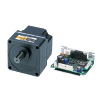
Brushless Motor and Driver
AXH Series
OPERATING MANUAL
Thank you for purchasing an Oriental Motor product.
This operating manual describes product handling procedures and safety precautions.
• Please read it thoroughly to ensure safe operation.
• Always keep the manual where it is readily available.
Table of contents
1 Introduction .................................. 2
2 Safety precautions ....................... 4
3 Preparation................................... 8
3.1
Checking the product .................. 8
3.2
Names and function of parts ..... 10
4 Installation ...................................11
4.1
Installation site .......................... 11
4.2
(gearhead) ................................ 11
4.3
Load installation ........................ 13
4.4
Driver installation ...................... 14
4.5
with EMC directive .................... 15
5 Connection..................................18
5.1
Motor connection...................... 18
5.2
Power connection..................... 19
5.3
output signal ............................. 20
5.4
Example connection ................. 21
5.5
signals ...................................... 22
6 Setting the running speed ...........27
7 Inspection....................................29
countermeasures ........................30
HM-5126-5
Advertisement
Table of Contents

Subscribe to Our Youtube Channel
Related Manuals for Oriental motor AXH Series


Summary of Contents for Oriental motor AXH Series
-
Page 1: Table Of Contents
Brushless Motor and Driver AXH Series OPERATING MANUAL Thank you for purchasing an Oriental Motor product. This operating manual describes product handling procedures and safety precautions. • Please read it thoroughly to ensure safe operation. • Always keep the manual where it is readily available. -
Page 2: Introduction
1 Introduction 1 Introduction The AXH series is a brushless DC motor adopting a thin, high torque motor and a 24 VDC input open case type high-precision driven. The product is available in three types; a round shaft type which is the optimum for high speed requirements and a ∗... - Page 3 1 Introduction Applicable Standards Certification Standards Applicable Standards Body File No. Motor: UL 1950 AXH015 type CSA C22.2 No.950 AXH230 type E208200 Driver: UL 60950-1 AXH450 type CSA C22.2 No.60950-1 UL 60950 AXH5100 type E208200 CSA C22.2 No.60950 • The names of products certified to conform with relevant standards are represented by applicable unit model motor and driver part numbers.
-
Page 4: Safety Precautions
2 Safety precautions 2 Safety precautions The precautions described below are intended to prevent danger or injury to the user and other personnel through safe, correct use of the product. Use the product only after carefully reading and fully understanding these instructions. Handling the product without observing the instructions that WARNING accompany a “Warning”symbol may result in serious injury or... - Page 5 2 Safety precautions Operation • Turn off the driver power in the event of a power failure, or the motor will suddenly start when the power is restored and may cause injury or damage to equipment. • Do not use it in a vertical applications. When the driver protection function is triggered, the motor will stop operating.
- Page 6 2 Safety precautions • Before moving the motor directly with the hands (as in the case of manual positioning), confirm that the driver operation input is “OFF” to prevent injury. • Do not perform the motor’s starting and stopping operations by turning the power on and off.
- Page 7 2 Safety precautions Noise measures The electrical noise is of two types: One is a noise to invade into the driver from the outside and cause the driver malfunction, and the other is a noise to emit from the driver and cause peripheral equipments malfunction. For the noise that is invaded from the outside, take measures to prevent the driver malfunction.
-
Page 8: Preparation
3 Preparation 3 Preparation The following describes the items to be confirmed, names and functions of individual components. 3.1 Checking the product Open the package and make sure that the following items are supplied. If there is any shortage or damage, contact the sales office where you bought the product. The unit model of the product you bought should be checked by reference to the model on the label of the package. - Page 9 3 Preparation Combinations of gearheads, motors and drivers Gearhead Driver ∗ ∗ Type Unit model Motor model model model AXH015K-A AXHM015K-A AXHD15K − AXH230KC-A AXHM230KC-A AXHD30K − Round shaft type AXH450KC-A AXHM450KC-A AXHD50K − AXH5100KC-A AXHM5100KC-A AXHD100K − AXH230KC-GFH AXHM230KC-GFH AXHD30K −...
-
Page 10: Names And Function Of Parts
3 Preparation 3.2 Names and function of parts The following describes the names and functions of individual components of the driver. For detailed information of each unit, see the page shown in the square bracket. Driver model: AXHD15K, AXHD30K, AXHD50K [P.19] Power connector (CN1) Connect the power cable. -
Page 11: Installation
4 Installation 4 Installation The following shows the motor (gearhead) and driver installation environment, installation method and load installation. 4.1 Installation site The motor (gearhead) and driver are designed and manufactured to be incorporated into the equipment. To ensure effective ventilation and easy inspection, install it in the following site. •... - Page 12 4 Installation • Round shaft type To install the motor, use the four installation holes and mount the motor with four bolts (not provided) so that there is no gap with the metallic plate. Refer to the gearhead instruction manual for mounting the pinion shaft type.
-
Page 13: Load Installation
4 Installation 4.3 Load installation When installing the load to the motor or gearhead, ensure that the motor output shaft or gearhead output shaft and load shaft are aligned with each other. Optional flexible couplings are available (sold separately). The output shaft of the round shaft type and geared type is provided with a flat. Use double point screws on the flat and provide reliable locking to prevent idle rotation of the load. -
Page 14: Driver Installation
4 Installation 4.4 Driver installation Direction of installation The driver is designed on the basis of heat radiation by air convection and heat conduction to the housing. When installing the driver in the housing, use four installation holes on the driver and install it in the vertical or horizontal direction. -
Page 15: Installing And Wiring In Compliance With Emc Directive
EN 61000-6-2 Installing and wiring Effective measures must be taken against the EMI that the AXH series may give to adjacent control-system equipment, as well as the EMS of the AXH series itself, in order to prevent a serious functional impediment in the machinery. - Page 16 4 Installation • Ferrite core • When suppressing effect by noise propagation, use a ferrite core. • Use the ferrite core for extending the motor cable Use ferrite core 7427122 by Wurth Electronik GmbH & Co. KG, ZCAT3035-1330 by TDK Corporation or its equivalent. Connect the ferrite cores as close as possible to the driver.
- Page 17 4 Installation • Others • Connect the motor, driver and other peripheral control equipment directly to the grounding point so as to prevent a potential difference from developing between grounds. • When relays or electromagnetic switches are used together with the system, use noise filters and CR circuits to suppress surges generated by them.
-
Page 18: Connection
5 Connection 5 Connection The following shows the method of connecting the driver and motor/power source/external controller, earth connection method, an example of connection and input/output signals. 5.1 Motor connection Insert the motor cable connector into the motor connector (AXH015/AXH230/ AXH450 type: CN3, AXH5100 type: CN3 and CN4) of the driver. -
Page 19: Power Connection
5 Connection 5.2 Power connection Input power voltage is 24 VDC±10%. Insert the power cable connector into the driver power connector (CN1). When you do not use the power cable supplied with to the product, use a cable with ) or more for AXH015/AXH230/ a diameter equivalent to AWG22 (0.3 mm AXH450 type, and use a AWG18 (0.75 mm ) for AXH5100 type. -
Page 20: Connection Of Input Signal And Output Signal
5 Connection 5.3 Connection of input signal and output signal Connection with driver Insert the connector of the input/output signal cable into the connector of the input/output signal cable (CN2) of the driver. Color indication represents the color of the attached cable. The connection of CN1 varies, depending on the output signal. -
Page 21: Example Connection
5 Connection 5.4 Example connection Input signal • Controller output: 5 V C-MOS • Controller output: open collector output Driver Driver internal connections internal connections +5 V +5 V +5 V START/STOP START/STOP RUN/BRAKE RUN/BRAKE CW/CCW CW/CCW 10 kΩ 10 kΩ Open INT.VR/EXT INT.VR/EXT... -
Page 22: Input Signals And Output Signals
5 Connection 5.5 Input signals and output signals Do not perform the motor’s starting and stopping operations by CAUTION turning the power on and off. Perform them by inputting START/STOP and RUN/BRAKE. This may cause injury or damage to the equipment. The input signals (START/STOP, RUN/BRAKE, CW/CCW, INT.VR/ EXT, Note •... - Page 23 5 Connection RUN/BRAKE input RUN is selected when the input is on (L level), and motor starts running. BRAKE is selected when the input is off (H level), and motor stops instantaneously. ∗ 10 ms minimum OFF "H" START/STOP input START STOP ON "L"...
- Page 24 5 Connection ALARM-RESET input When the motor is stopped, turn on this signal (L level); then turn it off (H level). This will allow ALARM to be reset. Before inputting the ALARM RESET, reset either the START/STOP or RUN/BRAKE input to the OFF (H level). If both are ON (L level), ALARM-RESET input will not be accepted.
- Page 25 5 Connection Timing chart Two-step speed selection, Run, Direction of rotation Stop Instantaneous stop selection ∗ 10 ms minimum High speed Low speed CW (Clockwise direction) Motor operating pattern CCW (Counterclockwise direction) OFF "H" ∗ START/STOP input START START ON "L" ∗...
- Page 26 5 Connection ALARM output The protection function of the driver activates in following cases, and the ALARM output is turned off (H level), thereby stopping the motor. In this case, you can check the contents of the protection function which was operating by the number of LED flashes.
-
Page 27: Setting The Running Speed
6 Setting the running speed 6 Setting the running speed In addition to the driver internal potentiometer, the external potentiometer or external DC voltage can be used to set the motor running speed. The motor speed range is from 100 to 3000 r/min for the case of the motor alone. Two running speeds can be set by combining the internal potentiometer and external potentiometer, or the internal potentiometer and external DC voltage. - Page 28 6 Setting the running speed • To set the running speed only by the external potentiometer, there is no problem if the INT.VR/EXT input is not connected. • To perform operation by switching the motor running speed, use the INT.VR/EXT to switch the external potentiometer and internal potentiometer. To use a shielded cable for connection with the external potentiometer, Note connection should be made close to the input/output signal cable connector.
-
Page 29: Inspection
7 Inspection 7 Inspection It is recommended to check the following four items after motor operation. If any failure is found, stop the operation, and please contact your local sales office. • Check if abnormal noise is produced from the motor bearing section (ball bearing). -
Page 30: Trouble Diagnosis And Countermeasures
8 Trouble diagnosis and countermeasures 8 Trouble diagnosis and countermeasures During motor running, the motor and driver may not operate correctly due to speed setting error or connection error. If normal motor operation cannot be ensured, see the following description and take appropriate countermeasures. If normal operation cannot be ensured even after that, please contact your local sales office. - Page 31 8 Trouble diagnosis and countermeasures Phenomenon Estimated cause Measure The motors driven in the CW direction when the CW/CCW input Incorrect CW/CCW input or is set to the L level. CCW direction faulty connection. when the CW/CCW input is set to The motor is the H level.
- Page 32 If a new copy is required to replace an original manual that has been damaged or lost, please contact your nearest Oriental Motor branch or sales office. • Oriental Motor shall not be liable whatsoever for any problems relating to industrial property rights arising from use of any information, circuit, equipment or device provided or referenced in this manual.
Need help?
Do you have a question about the AXH Series and is the answer not in the manual?
Questions and answers