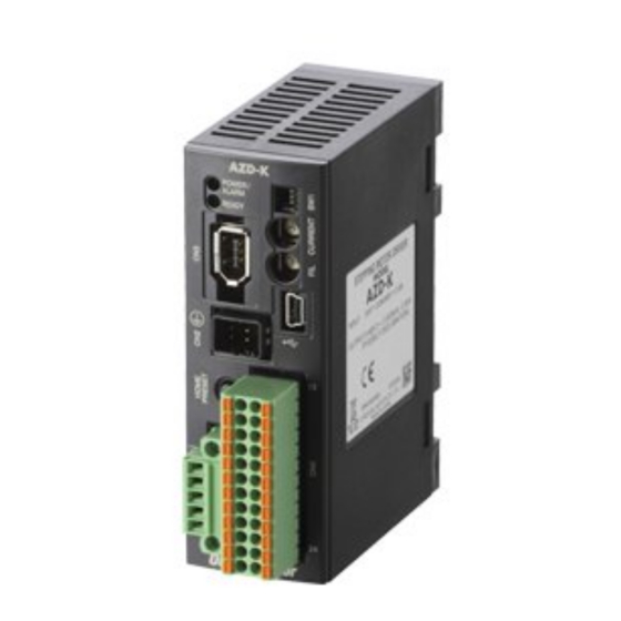
Oriental motor AZM14*K Series Operating Manual

Oriental motor AZM14*K Series Operating Manual

Stepping motor and driver package alphastep az series/motorized actuator equipped with az series dc power input

Advertisement

Stepping Motor and Driver Package
AZ Series/
Motorized actuator equipped with AZ Series
DC power input
Built-in controller type
 Pulse input type with RS-485 communication interface
 Pulse input type
OPERATING MANUAL Driver
MSIP-REM-OMC-088
1
Introduction ................................... 2
2
Safety precautions ........................ 5
3
Precautions for use ........................ 7
4
5
Preparation ..................................... 9
6
Installation .................................... 12
7
Connection ................................... 14
8
9
Setting ........................................... 28
Thank you for purchasing an Oriental Motor product.
This Manual describes product handling procedures and safety precautions.
 Please read it thoroughly to ensure safe operation.
 Always keep the manual where it is readily available.
10 Guidance ....................................... 32
11 Inspection ..................................... 43
13 Troubleshooting .......................... 45
convenient manners ................... 47
15 Accessories.................................... 48
HM-60315-2

Advertisement

Table of Contents
loading
Need help?

Need help?

Do you have a question about the AZM14*K Series and is the answer not in the manual?

Questions and answers

Summary of Contents for Oriental motor AZM14*K Series

  • Page 1: Table Of Contents

    HM-60315-2 Stepping Motor and Driver Package AZ Series/ Motorized actuator equipped with AZ Series DC power input  Built-in controller type  Pulse input type with RS-485 communication interface  Pulse input type OPERATING MANUAL Driver MSIP-REM-OMC-088 Introduction ........2 10 Guidance ........
  • Page 2: Introduction

    Introduction Introduction  Before use Only qualifi ed personnel of electrical and mechanical engineering should work with the product. Use the product correctly after thoroughly reading the “2 Safety precautions” on p.5. In addition, be sure to observe the contents described in warning, caution, and note in this manual. The product described in this manual has been designed and manufactured to be incorporated in general industrial equipment.
  • Page 3 Introduction  About terms and units Terms and units to be used vary depending on a motor or motorized actuator. This manual explains by using the terms of the motor. When the motorized actuator is used, read this manual by replacing the terms. Motor Motorized actuator Torque...
  • Page 4 Introduction  Types and overview of driver There are 3 types of drivers in the AZ Series as shown below. I/O signals, setting items, and LEDs vary depending on the driver type. Built-in controller type Function setting switch Protocol Address number (extended) POWER/ALARM LED Address number C-DAT/C-ERR LED...
  • Page 5: Safety Precautions

    Safety precautions Safety precautions The precautions described below are intended to prevent danger or injury to the user and other personnel through safe, correct use of the product. Use the product only after carefully reading and fully understanding these instructions. Description of signs Handling the product without observing the instructions that accompany a "Warning"...
  • Page 6 Safety precautions  Do not use the product beyond its specifi cations. This may cause electric shock, injury or damage to equipment.  Keep your fi ngers and objects out of the openings in the product. Failure to do so may result in fi re, electric shock or injury.
  • Page 7: Precautions For Use

    Precautions for use Precautions for use This section covers limitations and requirements the user should consider when using the product.  Always use the accessory cable to connect the motor and driver.  When conducting the insulation resistance measurement, be sure to separate the connection between the motor and the driver.
  • Page 8: Regulations And Standards

    Regulations and standards Regulations and standards EU Directive  CE Marking This product is affixed the CE Marking under the EMC Directive.  Low Voltage Directive The input power supply voltage of this product is 24 VDC/48 VDC. Therefore this product is not subject to the Low Voltage Directive, but install and connect it as follows.
  • Page 9: Preparation

    Preparation Preparation This chapter explains the items you should check, as well as the name and function of each part. Checking the product Verify that the items listed below are included. Report any missing or damaged items to the branch or sales offi ce from which you purchased the product.
  • Page 10 Preparation  Connector, terminal Names, indication, and functions for connectors and terminals are common to all drivers. The RS-485 communication connectors (CN6 and CN7) are not provided in the pulse input type drivers. Name Display Description Encoder connector Connects the encoder. Connects the motor.
  • Page 11 Preparation  Pulse input type Name Display Description  This LED is lit in green while the power is input.  If an alarm (protective function) generates, the LED will blink in red. POWER/ALARM LED POWER/ALARM  If an information generates, the LED will blink in red and green (Green/Red) simultaneously.
  • Page 12: Installation

    Installation Installation This chapter explains the installation location and installation method of the driver. Location for installation The driver has been designed and manufactured to be incorporated in equipment. Install it in a well-ventilated location that provides easy access for inspection. The location must also satisfy the following conditions: ...
  • Page 13 Installation Removing from DIN rail Pull the DIN lever down until it locks using a fl at tip screwdriver, and lift the bottom of the driver to remove it from the rail. Use force of about 10 to 20 N (2.2 to 4.5 lb.) to pull the DIN lever to lock it. Excessive force may damage the DIN lever.
  • Page 14: Connection

    Connection Connection This chapter explains how to connect the motor, power supply and I/O signals to the driver, as well as grounding method. Connection method The following fi gure shows models for the electromagnetic brake type. Connect to CN3 Cable for encoder Connect to CN2 Cable for motor Connect to CN4...
  • Page 15 Connection Connecting the power supply and grounding Power supply connection terminals and a protective earth terminal are provided in the CN1 connector. The applicable wire size varies between lead wires for a power supply and protective earth. Be sure to use proper lead wires. ...
  • Page 16 Connection  Pin assignment list  Built-in controller type Signal name Description * Signal name Description * Control input 0 (START) Control input 1 (M0) Control input 2 (M1) Control input 3 (M2) Control input 4 (ZHOME) Control input 5 (FREE) Control input 6 (STOP) Control input 7 (ALM-RST) IN-COM [0-7] IN0 to IN7 input common...
  • Page 17 Connection Connection diagram  Connecting to a current sink output circuit The fi gure below shows a connection example of the built-in controller type driver. In the case of the pulse input type with RS-485 communication interface and the pulse input type, the pin No.1, No.2, No.13, and No.14 are only available to the pulse input.
  • Page 18 Connection  Use input signals at 24 VDC.  Use output signals at 12 to 24 VDC, 10 mA or less. If the current exceeds 10 mA, connect an external resistor R0 so that the current becomes 10 mA or less. ...
  • Page 19 Connection  Connecting to a current source output circuit The fi gure below shows a connection example of the built-in controller type driver. In the case of the pulse input type with RS-485 communication interface and the pulse input type, the pin No.1, No.2, No.13, and No.14 are only available to the pulse input.
  • Page 20 Connection  Use input signals at 24 VDC.  Use output signals at 12 to 24 VDC, 10 mA or less. If the current exceeds 10 mA, connect an external resistor R0 so that the current becomes 10 mA or less. ...
  • Page 21 Connection Connecting the RS-485 communication cable Connect this cable if you want to control your product via Drivers can be linked. RS-485 communication. Connect the RS-485 communication cable to CN6 or CN7 on the driver. You can use the vacant connectors to connect a diff erent driver.
  • Page 22 Connection Noise measures The electrical noise is of two types: One is a noise to invade into the driver from the outside and cause the driver malfunction, and the other is a noise to emit from the driver and cause peripheral equipments malfunction. For the noise that is invaded from the outside, take measures to prevent the driver malfunction.
  • Page 23 Connection  Noise suppression parts (accessories) Refer to p.48 for accessories.  Driver cable This cable is a shielded cable for good noise immunity to connect the driver and controller. The ground wires useful to grounding are provided at both ends of the cable. The EMC measures are conducted using the Oriental Motor driver cable.
  • Page 24 Connection  Example of motor and driver installation and wiring The driver uses parts that are sensitive to electrostatic charge. Take measures against static electricity since static electricity may cause the driver to malfunction or suff er damage. Built-in controller type, pulse input type with RS-485 communication interface RS-485 Controller communication cable...
  • Page 25: Explanation Of I/O Signals

    Explanation of I/O signals Explanation of I/O signals Input signals The following input signals of the driver are photocoupler inputs. The signal state represents the "ON: Carrying current" or "OFF: Not carrying current" state of the internal photocoupler rather than the voltage level of the signal. ...
  • Page 26 Explanation of I/O signals  M0, M1, M2 input Select a desired operation data number based on a Operation data No. combination of ON/OFF status of the M0 to M2 inputs.  ZHOME input When the ZHOME input is turned ON, the motor will move to the home position set by the HOME PRESET switch or MEXE02.
  • Page 27 Explanation of I/O signals Output signals The driver outputs signals in the photocoupler/open-collector output mode or line driver output mode. The signal state represents the "ON: Carrying current" or "OFF: Not carrying current" state of the internal photocoupler rather than the voltage level of the signal. ...
  • Page 28: Setting

    Setting Setting This chapter explains how to set the motor and driver functions. Setting of the built-in controller type and pulse input type with RS- 485 communication interface The fi gure shows the built-in controller type driver. Function setting switch (SW1) No.3, No.4: Sets the Termination resistor.
  • Page 29 Setting  Protocol Set the protocol of RS-485 communication using the SW1-No.2 of the function setting switch. Factory setting Built-in controller type; OFF Pulse input type with RS-485 communication interface; ON SW1-No.2 Protocol Modbus RTU mode Connecting with network converter ...
  • Page 30 Setting Setting of the pulse input type Function setting switch (SW1) No.3, No.4: Not used. No.2: Sets the pulse input mode. No.1: Sets the resolution. Current setting switch (CURRENT) Command filter setting switch (FIL) →ON Be sure to turn off the driver power before setting the function setting switch (SW1). The new setting of the SW1 will become eff ective after the power is cycled.
  • Page 31 Setting The motor torque is proportional to the current. If the CURRENT switch is set to "7" (50%) while the operating torque is set to 100% (maximum output current), only 50% of the torque is output. Base current rate 100% Base current rate 50% Rotation speed [r/min] ...
  • Page 32: Guidance

    Guidance 10 Guidance If you are new to the AZ Series, read this section to understand the operating methods along with the operation fl ow.  How to read the guidance This chapter explains the operation procedure as follows.  Connection ( p.32) ...
  • Page 33 Guidance 10-2 Home position setting The home position has not set at the time of shipment. Before starting operation, be sure to set the home position. Perform the home position setting only once initially. Once the home position is set, the driver keeps the home information even if the power supply is shut down.
  • Page 34 Guidance 4. Click "Start the teaching remote operation." The pop-up window (Warning) appears, and click [Yes]. 5. Since the window which uses to synchronize the MEXE02 data and the driver data appears, select the synchronization method and click [OK]. Teaching, remote operation is enabled, and red color and green color on the POWER/ALARM LED blink simultaneously.
  • Page 35 Guidance 7. When adjusting the motor position manually, click [FREE: ON] fi rst, and click [Yes] on the pop-up window (Warning). The holding power of the motor output shaft is lost, and the output shaft can be turned by hand. After adjustment, click [FREE: OFF], and recover the motor excitation.
  • Page 36 Guidance Description of JOG operation switches Switch Description Performs continuous operation in the negative direction at the operating speed set in the "(JOG) Operating speed (high)" parameter. Performs continuous operation in the negative direction at the operating speed set in the "(JOG) Operating speed"...
  • Page 37 Guidance 10-4 Positioning operation This section explains an example to perform positioning operation using the MEXE02. When using the pulse input type, set operation data to the programmable controller to perform operation. Before operating the motor, check the condition of the surrounding area to ensure safety. Set the operation data using the MEXE02 STEP 1 Using the MEXE02, set the operation data of No.0 as follows.
  • Page 38 Guidance 3. Write the edited data to the driver. Click "Writing all data. (PC −> Product)," and click [OK]. The contents of the data No.0 will be written to the driver. 4. Click [Start positioning operation]. The pop-up window (Warning) appears, and click [Yes]. The motor performs positioning operation.
  • Page 39 Guidance 2. After the motor returns to the home position, check that the "Command position" is 0.  When changing the operating condition of high-speed return-to-home operation 1. Click on “Motor & Mechanism(Coordinates/JOG/Home Operation)” under “Parameter, ” in the left side of the screen. The “Motor &...
  • Page 40 Guidance 10-6 Timing chart This section shows ON/OFF timings for input signals and output signals. For details, check with the AZ Series Function Edition.  Positioning operation  Built-in controller type Positioning operation can be performed with selecting the operation data. 1.
  • Page 41 Guidance  When using in the 1-pulse input mode. Perform the following settings beforehand when using in the 1-pulse input mode. Pulse input type with RS-485 communication interface; 1. Click on “Communication I/F function” under “Parameter, ” in the left side of the screen. The “Communication I/F function”...
  • Page 42 Guidance  High-speed return-to-home operation (ZHOME operation) High-speed return-to-home operation is used to return to the home position that is set by the MEXE02 or HOME PRESET switch. 1. Turn on the power supply. The READY output and PLS-RDY output turn ON. 2.
  • Page 43: Inspection

    Inspection 11 Inspection It is recommended that periodic inspections be conducted for the items listed below after each operation of the motor. If an abnormal condition is noted, discontinue any use and contact your nearest Oriental Motor sales offi ce. ...
  • Page 44: Alarm (Protective Function)

    Alarm (protective function) 12 Alarm (protective function) When an alarm generates, the ALM-B output will turn OFF and POWER/ALARM LED will blink in red. Before resetting an alarm, always remove the cause of the alarm and ensure safety. If the motor cannot be operated properly after resetting the alarm, the driver may have been damaged. For details about alarms, refer to the AZ Series Function Edition.
  • Page 45: Troubleshooting

    Troubleshooting 13 Troubleshooting During motor operation, the motor or driver may fail to function properly due to an improper setting or wiring. When the motor cannot be operated correctly, refer to the contents provided in this section and take appropriate action. If the problem persists, contact your nearest Oriental Motor sales office.
  • Page 46 Troubleshooting  Check the alarm message using the MEXE02 when the alarm generates.  I/O signals can be monitored using the MEXE02. Use to check the wiring condition of the I/O signals. ▌46...
  • Page 47: To Use The Product In More Convenient Manners

    To use the product in more convenient manners 14 To use the product in more convenient manners Using the MEXE02, you can set the operation data or change I/O signals that assign to the CN4 connector. Also, you can monitor the operating status or perform test operation. Refer to the AZ Series Function Edition for details about operation.
  • Page 48: Accessories

    Accessories 15 Accessories 15-1 Motor cable set  Connection cable (for AZM14, AZM15, AZM24, AZM26) This is a cable needed when a motor and driver are connected. Connection cable When installing the motor on a moving part, use a fl exible cable having excellent fl ex resistance. ...
  • Page 49 Accessories  Connection cable set (for AZM46, AZM48, AZM66, AZM69) This is a cable set needed when a motor and driver are connected. It is a set of two cables for the motor and encoder. For the cable set of electromagnetic brake motors, a set of three cables for the motor, encoder and electromagnetic brake is provided.
  • Page 50 Accessories  Flexible connection cable set For standard type motor For electromagnetic brake type motor Model Length [m (ft.)] Model Length [m (ft.)] CC050VZR2 CC050VZRB2 0.5 (1.6) 0.5 (1.6) CC010VZR2 CC010VZRB2 1 (3.3) 1 (3.3) CC015VZR2 CC015VZRB2 1.5 (4.9) 1.5 (4.9) CC020VZR2 CC020VZRB2 2 (6.6)
  • Page 51 Accessories  Extension cable set (for AZM46, AZM48, AZM66, AZM69) This is a cable set needed when a motor and driver are relayed. Use when extending the distance a motor and a driver or when the length of the connection cable used is not enough.
  • Page 52 Accessories 15-2 Driver cable This cable is a shielded cable for good noise immunity in order to connect the I/O signals of the controller to the driver. The ground wires useful to grounding are provided at both ends of the cable. A connector is assembled at the driver side.
  • Page 53 53▐...
  • Page 54 ▌54...
  • Page 55 55▐...
  • Page 56 • Please contact your nearest Oriental Motor office for further information. Technical Support Tel:(800)468-3982 Singapore Korea Tel:1800-8420280 Tel:080-777-2042 8:30 to 5:00 , P.S.T. (M-F) A.M. P.M. www.orientalmotor.com.sg www.inaom.co.kr 7:30 to 5:00 , C.S.T. (M-F) A.M. P.M. www.orientalmotor.com Tel:1800-806161 Hong Kong Branch Tel:+55-11-3266-6018 www.orientalmotor.com.my...

Table of Contents