
Related Manuals for ECR International 550003792


Summary of Contents for ECR International 550003792
- Page 1 Domestic Hot Water Module # 550003792 INSTALLATION, OPERATION & MAINTENANCE MANUAL ECR International Inc. 2201 Dwyer Avenue, Utica, NY 13501 Tel. 800 253 7900 www.ecrinternational.com PN 240012960 REV. F [09/15/2020]...
-
Page 2: Important Safety Information
FOR YOUR SAFETY READ BEFORE INSTALLATION AND OPERATION DANGER IMPORTANT SAFETY INFORMATION Installation shall be completed by qualified agency. WARNING Fire, explosion, asphyxiation and electrical shock hazard. Improper installation could result in death or serious injury. Read this manual and understand all requirements before beginning installation. - Page 3 • Before carrying out any cleaning or maintenance, WARNING turn off the appliance at the power supply by Burn and scald hazard. Components shall be operating the circuit breaker, and from the water installed by qualified service agency in accordance supply using the appropriate stopcocks.
-
Page 4: Table Of Contents
CONTENTS Important Safety Information ......................2-3 Specifications ..........................5 Main Components ..........................7 Installation ............................7 Hydraulic Connections........................9 Electrical Connections ........................12 Start Up ............................12 Operation and Use.......................... 13 User Interface..........................15 Mechanical Drawings ........................18 Internal Wiring..........................19 Maintenance ..........................19 Spare Parts List ..........................21 Troubleshooting .......................... -
Page 5: Specifications
The module is mounted on a wall near the boiler. Rated Thermal Product Range Btu/h (kW) DHW MODULE 550003792 228,000 (67) 11.81 " (300 mm) 12 " (305 mm) 3.74 " (95 mm) 7.87 "... - Page 6 Technical Specifications Materials Transfer Fluid Water Components Brass EN 12165 CW617N-DW Maximum glycol percentage* Connection pipes Copper Maximum fluid temperature 194°F / 90° C Frame Galvanized steel 43.5 psi (3 bar) Boiler Water Insulation Maximum Operating 145 psi (10 bar) Domestic Heat Exchanger Brazed stainless steel...
-
Page 7: Main Components
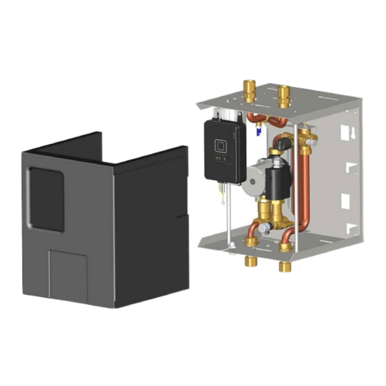
MAIN COMPONENTS CH Inlet CH Outlet DHW Inlet DHW Outlet Two Way Valve Temperature Sensor T1 Electronic Control Regulator (REC) Plate Heat Exchanger Stepper Motor Wilo Pump Star 21U15-130 DHW Flow Meter Steel Frame DHW Flow Sensor DHW Flow Regulator Pipe Adapter Unions (4) Drain Tap Air Vent... - Page 8 Water Quality • If the CH water (i.e. boiler water) is very hard or full of impurities, it must be adequately filtered and treated, otherwise damage and/or malfunction could be caused. Recommended water quality is: o Hardness Less than 8.8 grains per gallon (150 mg/L) o Acidity level 7-8 pH o Sediments...
-
Page 9: Hydraulic Connections
HYDRAULIC CONNECTIONS NOTICE When the system requires the domestic hot water circuit to have a device which prevents water expansion towards the mains (non-return valve, meter, pressure reducer, etc.) it is necessary to install an expansion tank downstream of the device. - Page 10 Charts below show the pressure drop through the DHW circuit of the DHW module. PN 240012960 REV. F [09/15/2020]...
- Page 11 CH Circuit • Piping diameter shall not be reduced from the DHW module’s provided 3/4" connection size. • Piping to and from the boiler should be kept as short as possible with minimum number of restrictions such as elbows in order to maximize CH flow and DHW output. •...
-
Page 12: Electrical Connections
ELECTRICAL CONNECTIONS • Electrical wiring shall conform to the requirements of the authority having jurisdiction, or in the absence of such requirements, to the National Electrical Code ANSI/NFPA 70 (United States) or Canadian National Electrical Code CSA C22 (Canada). • Power supply is 115 volts, 60 hertz, single phase, less than 2 amps. -
Page 13: Operation And Use
OPERATION AND USE The DHW Module shall be piped to a boiler that incorporates a low limit control to maintain boiler water temperature. Limit settings may be varied to meet the requirements of the installation. The low limit setting shall be at least 10°F (5.5 °C) below the high limit setting for proper operation. - Page 14 Temperature Regulation The set point temperature T1 of the DHW fluid at the heat exchanger outlet is factory set to the default value of 122 °F (50°C). The REC is equipped with trimmer P1, accessible by removing the rubber plug located on the front cover, with which the temperature T1 can be adjusted to a value different from the factory setting.
-
Page 15: User Interface
USER INTERFACE The user interface integrated in the REC consists of the following devices: • LCD Display Shows programmed DHW set-point temperature T1 and fault codes. The display can be either degrees Fahrenheit (display shows three digits) or Celsius (display shows two digits). The factory setting is Fahrenheit. See Dip Switch section below (dip switch 4) to change display settings. - Page 16 • Dip Switches The dip switches are located on the control board inside the REC. The factory configuration is: switches 1-5 in the OFF position and switch 6 in the ON position. Switch 4 toggles the display between Fahrenheit and Celsius. All other switches must remain in their factory configuration.
- Page 17 Fault Codes The FAULT led indicates the following faults • Temperature Sensor T1 Fault, code 6 on the LCD display If the T1 sensor fails it immediately interrupts the domestic hot water supply. The fault is indicated by blinking FAULT led and shown on the LCD display with the blinking code 6. The normal operating condition is automatically enabled by restoring the correct functionality of the sensor.
-
Page 18: Mechanical Drawings
MECHANICAL DRAWINGS 4.33" (110 mm) 3.74" (95 mm) 3.74" (95 mm) 9.29" (236 mm) 1.26" (32 mm) 1.26" (32 mm) 3.74" (95 mm) 4.33" (110 mm) 3.74" (95 mm) PN 240012960 REV. F [09/15/2020]... -
Page 19: Internal Wiring
INTERNAL WIRING Electronic Regulator Temperature Sensor Flow Sensor Two-Way Valve Motor Power Supply Pump Earth MAINTENANCE • Maintenance and troubleshooting shall be performed by qualified technical personnel. • Regular maintenance ensures better efficiency and helps to save energy. • Use original spare parts for efficient operation and safety of the appliance. •... - Page 20 MAINTENANCE Replacing the Heat Exchanger Remove the heat exchanger A by unscrewing the two fixing socket head screw VF. Proceed by replacing the heat exchanger and o-rings. Place the plate heat exchanger with the arrows of first corrugated plate towards the top. Screw 2 screws VF -torque: 31 ±...
-
Page 21: Spare Parts List
SPARE PARTS LIST Component Item Description Part No. Plate heat exchanger SWEP ET8AS-22P 240012943 Plate heat exchanger screw SOCKET HEAD SCREW M5X16 201000156 Plate heat exchanger O-ring O-RING 3.6X18.3X25.5 240012944 Pump Wilo Star 21U-15-130 240012945 Two way valve cartridge 240012946 Stepper motor Sonceboz 7217R901 102000194... -
Page 22: Troubleshooting
TROUBLESHOOTING Description Warnings Possible cause of the problem Things to try Problem Power supply interrupted Restore power supply All LEDs are off REC fuse blown Replace fuse Faulty REC Replace the REC Temperature sensor is disconnected Insert connector Faulty temperature sensor Replace sensor FAULT LED flashing Reset dipswitches 1-2-3 to OFF,... - Page 23 International, Inc. (“ECR”) issues limited warranties from the all labor and material costs connected therewith, including, date of installation of the applicable ECR International without limitation, costs associated with supplying/returning Domestic Hot Water Module (DHW Module) to the Original the defective part to ECR.
-
Page 24: Warranty
Web: www.ecrinternational.com in writing. PN 240012449, Rev. B 2201 Dwyer Avenue, Utica, NY 13501 All specifications subject to change without notice. Tel. 800 253 7900 ©2020 ECR International, Inc. - 2 - www.ecrinternational.com BDR THERMEA GROUP...
Need help?
Do you have a question about the 550003792 and is the answer not in the manual?
Questions and answers