Advertisement
Quick Links
RSA-34
Published and distributed by:
CBS ArcSafe®
2616 Sirius Road
Denton, Texas 76208
A division of:
Distance
GroupCBS, Inc.®
P.O. Box 1557
Gainesville, Texas 76241
®
Copyright CBS ArcSafe
2019
Printed in the United States of America
Reproduction, adaptation, or translation without prior written permission is prohibited except as is allowed by law.
is
|
2616 Sirius Road
Denton, TX 76208
Safety
®
|
(877) 4-SAFETY
Rev. 3
For GE 7098 MCC
W H A T S T A N D S
B E T W E E N Y O U A N D
A R C - F L A S H D A N G E R ?
|
www.cbsarcsafe.com
WE
DO.
Advertisement

Related Manuals for CBS ArcSafe RSA-34


Summary of Contents for CBS ArcSafe RSA-34
- Page 1 B E T W E E N Y O U A N D Gainesville, Texas 76241 A R C - F L A S H D A N G E R ? ® Copyright CBS ArcSafe 2019 Printed in the United States of America 2616 Sirius Road...
- Page 2 RRS-4 – PLC Based Universal Remote Racking System (Rotary) The CBS ArcSafe® RRS-4 universal remote racking system is an updated PLC based version of the best selling RRS-1. The dual mode, source programmable, PLC based control system offers two different operating modes to choose from based on user preference or the application.
-
Page 3: Installation
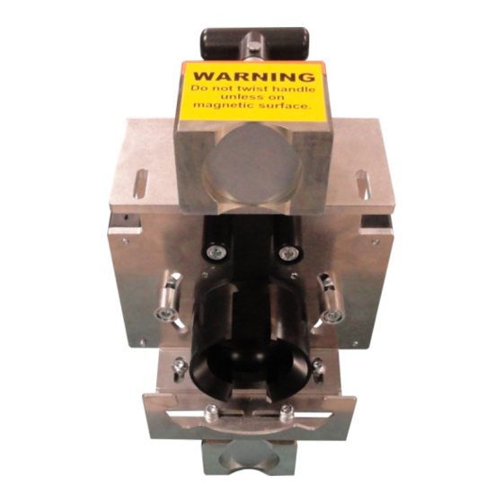
Figure 1 - Handle operator with clearance for RSA-34 installation Jog the RSA-34 motor arm into the correct position based on the current position of the MCC handle op- erator. If the stops have been properly adjusted, the operator may jog the motor arm until it is resting flush against the applicable stop, as shown in Figure 2. - Page 4 Figure 2 - RSA-34 motor arm jogged into position against hardstop Once the motor arm has been jogged to the correct position, the RSA-34 may be fitted to the handle op- erator. Place the RSA-34 over the handle operator and press the device against the switchgear. Ensure that both magnets sit flush against the cabinet and that the locator on the top side of the RSA fits cor- rectly over the handle operator’s position indicator as shown in the image below.
- Page 5 TTENTION Please ensure that all cables are clear of moving parts. Failure to do so could damage cables and/or actuator. The RSA-34 is now installed and ready for operation. Please see the following section for operational in- structions. RSA-34 Installation and Operation...
-
Page 6: Operation
1. Ensure that the RSA is properly installed on the handle operator as described in the previous sec- tion. 2. With the RSA-34 properly installed, open the RSO-I AR and connect the four pin threaded style connector from the RSO-1 AR to the RSA-34 motor control box. -
Page 7: Travel Adjustment
3.1 Travel Adjustment To adjust the travel of the motor arm of the RSA-34, the adjustable hard stops must be repositioned to allow for this modified travel range. The following image shows the available adjustment of these stops. Figure 4 - Travel adjustment of the motor arm To adjust the stops, loosen the nut and bolt which holds them in place and reposition as necessary. - Page 8 Figure 5 - Height adjustment on the top side of the RSA-34 Figure 6 - Height adjustment on the bottom side of the RSA-34 RSA-34 Installation and Operation...
- Page 9 3.3 Magnet Location Adjustment Both the upper and the lower magnet on the RSA-34 may be adjusted side to side to allow for any ob- structions that may not be moved. The following images will show the side to side adjustment of each magnet.
- Page 10 Notes RSA-34 Installation and Operation...
- Page 12 RSA-34 Installation and Operation 2616 Sirius Road Denton, TX 76208 Tel: 877-4-SAFETY Fax: 940-382-9435 Website: www.CBSArcSafe.com Email: info@CBSArcSafe.com ANGER Ensure that personnel using this equipment are adequately trained in the operation of the switchgear they are planning to work with; that they are correctly stationed outside the arc flash boundary;...
Need help?
Do you have a question about the RSA-34 and is the answer not in the manual?
Questions and answers