Table of Contents
Advertisement
Quick Links
OPERATING AND MAINTENANCE MANUAL
Product:
Type:
DESIGNED AND MANUFACTURED IN THE UK BY:
T & R Test Equipment Limited
15-16 Woodbridge Meadows, Guildford, Surrey, GU1 1BJ, United Kingdom
Telephone:
01483 207428
Fax.:
01483 511229
High Voltage AC Test Set
KV30-100 mk2
KV50-100 mk2
KV50-200 mk2
KV100-100 mk2
low discharge (LD) and timer (T) options
1
e-mail:
sales@trtest.com
Web:
www.trtest.com
Advertisement
Table of Contents

Subscribe to Our Youtube Channel
Related Manuals for T&R KV mk2 Series


Summary of Contents for T&R KV mk2 Series
- Page 1 OPERATING AND MAINTENANCE MANUAL Product: High Voltage AC Test Set Type: KV30-100 mk2 KV50-100 mk2 KV50-200 mk2 KV100-100 mk2 low discharge (LD) and timer (T) options DESIGNED AND MANUFACTURED IN THE UK BY: T & R Test Equipment Limited 15-16 Woodbridge Meadows, Guildford, Surrey, GU1 1BJ, United Kingdom Telephone: 01483 207428 e-mail:...
- Page 2 GENERAL SAFETY STATEMENT The following safety precautions should be reviewed to avoid injury to the user and damage to the product (and other products connected to it). To avoid potential hazards only use this product as specified. Only suitably qualified personnel should use this equipment. Servicing of this product should only be carried out by suitably qualified service personnel.
- Page 3 HIGH VOLTAGE SAFETY It is essential to follow safe working procedures when working with high voltage. Information on accepted codes of practice should be obtained from your local heath and safety regulatory body. It is essential that the KV100-100 mk2 series test sets are only used in a suitable test environment.
- Page 4 SAFETY TERMS AND SYMBOLS The following safety symbols appear on the equipment: CAUTION/WARNING – Refer to manual DANGER – High voltage Mains off Mains on The following safety symbols appear in this manual: This action or procedure may be dangerous if not carried CAUTION out correctly, and may cause damage to the equipment or connected equipment.
-
Page 5: Table Of Contents
CONTENTS DESCRIPTION OF EQUIPMENT Electrical Specification 1.1.1 Input and Output 1.1.2 Partial Discharge Level Front Panel Controls 1.2.1 Standard Units Without Timer 1.2.2 -T units With Test Timer Rear Panel Connections 1.3.1 Alarm Sounder 1.3.2 Signal Beacons 1.3.3 Earthing Mechanism Control Output Output Voltage Control Overload Protection 1.5.1... - Page 6 1.11 Construction 1.11.1 Control Unit 1.11.2 HV Transformer OPERATION Safety 2.1.1 Installation 2.1.2 Operation Connections Method of Operation MAINTENANCE Output Control Variable transformers HV Output Transformer ACCESSORIES Standard Accessories Optional Accessories OVERALL PERFORMANCE SPECIFICATION Insulation resistance at 1000V DC Applied voltage test 5.3.
-
Page 7: Description Of Equipment
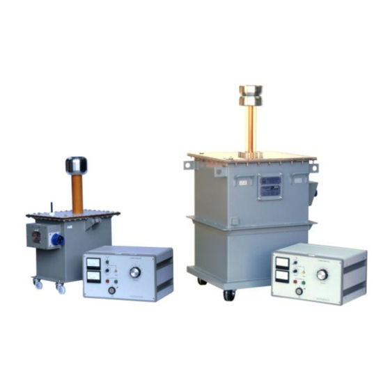
DESCRIPTION OF EQUIPMENT The KV series of high voltage test systems consist of a separate control unit and high voltage transformer. In addition, low partial discharge systems (-LD suffix on unit name) have a brush noise filter which is fitted in the power lead between the control unit and HV transformer. Units with test timer option (-T suffix on unit name) have a test timer fitted that sounds an alarm at the end of the preset test period. -
Page 8: Partial Discharge Level
1.1.2 Partial Discharge Level The partial discharge of the standard units in the KV series range is not specified. Two models in the range (the KV50-200LD and KV100-100LD) have specified partial discharge levels and are supplied with a brush noise filter to prevent noise from the supply and control unit variable transformer being transmitted through to the HV output. -
Page 9: Front Panel Controls
Front Panel Controls 1.2.1 Standard Units Without Timer Figure 1.1 Control panel front panel layout kV meter* HV output on switch and indicator kV meter range switch Supply indicator Emergency stop button Supply on/off switch E-stop/interlock reset button mA meter range switch Output control knob Variable overload trip reset switch Fixed overload circuit breaker... -
Page 10: T Units With Test Timer
1.2.2 -T units With Test Timer Figure 1.2 Control panel front panel layout (-T versions) kV meter* HV output on switch and indicator kV meter range switch Supply indicator Emergency stop button Supply on/off switch E-stop/interlock reset button mA meter range switch Output control knob Variable overload trip reset switch Fixed overload circuit breaker... -
Page 11: Rear Panel Connections
Rear Panel Connections Fig. 1.3 Rear panel connections Note: KV30-100 has different style connector Signal beacons & earthing Output to HV transformer mechanism control outputs Note: KV30-100 fitted with 3 pin connector. Contactor fault alarm sounder Main earth terminal Interlock & emergency stop circuit Mains supply lead inputs HV transformer voltage &... -
Page 12: Earthing Mechanism Control Output
Fig. 1.4 Signal lamps and earthing mechanism arrangement The green signal lamps are illuminated when the mains supply to the unit is on, and the key switch on the front panel (item K in Fig. 1.1) is off (ready for operation). The red signal lamps are illuminated when the key switch is on, all interlock switches closed, all emergency stop buttons released and the interlock circuit reset by pressing the front panel button (item D in Fig. -
Page 13: Overload Protection
Overload Protection The equipment is fitted with fixed and variable overload protection circuits as standard. 1.5.1 Fixed Overload The fixed overload protection system senses any rapid increase in the load current which exceeds approximately 120% of the full load current in the high voltage circuit. The circuit will respond more quickly to low impedance faults. -
Page 14: Metering
Metering The KV mk2 series range use a tap on the secondary of the HV transformer for voltage metering. This can be more accurate than primary metering, although capacitive loads will still cause the meter to read low. If very accurate kV metering is required, it is necessary to use an external HV divider. -
Page 15: Test Timer (-T Suffix Units Only)
Test timer (-T suffix units only) The test timer fitted to –T units may be pre-set with a test time in hours, minutes and seconds. The timer counts down when the output is switched on and an alarm sounds when the timer reaches zero. -
Page 16: Interlock Circuits
Interlock Circuits 1.8.1 Zero Voltage Interlock The equipment is fitted with a zero volt interlock system on the output voltage control. This interlock prevents the output being energised unless the output control is in the zero position. 1.8.2 External Interlock/Emergency Stop Circuit The equipment is fitted with an external, dual channel interlock system with safety monitoring. -
Page 17: Output Configuration
Output Configuration Note: The circuits shown below show a simplified arrangement. A full circuit diagram of the unit may be found at the rear of the manual. 1.9.1 HT Transformer Terminals Screen 1 Screen between primary winding and core Screen 2 Screen between primary and secondary windings. -
Page 18: Brush Noise Filter (Low Partial Discharge Units Only)
1.10 Brush Noise Filter (Low Partial Discharge Units Only) The KV50-200LD and KV100-100LD units are supplied with a brush noise filter to prevent interference and noise from the control unit variable transformer and supply affecting the output from the HV transformer. The brush noise filter is connected in the power lead between the control unit and the HV transformer. -
Page 19: Operation
OPERATION Safety The outputs from the KV series are extremely dangerous, and if used incorrectly could be fatal. The unit must only be installed, operated, and maintained by suitably qualified and trained personnel. It is essential to follow accepted safety procedures and local health and safety regulations and guidelines when installing and operating high voltage equipment. - Page 20 2.1.2.1 Interlocks The unit is provided with a dual channel external interlock circuit that may be used to link to interlock switches on the high voltage test area. The test area must be interlocked. An interlock should be considered to be a safety back-up feature. An interlock should not be regarded as a substitute for adequate safety rules and proper operator vigilance.
- Page 21 also provide a conservative functional clearance to earth for high voltage components in the test area. Particular attention should be paid to clearances between any parts of the test object at test voltage potential and the test enclosure or barriers. Refer to EN50191:2001 and local safety standards for details of the safety clearances required.
-
Page 22: Connections
Connections Before making any connections please ensure that you are aware of all hazards relating to the system and environment in which it is operating. The test object must be isolated, proved to be dead and earthed before any connections are made. - Page 23 Note: HV connection lead and earth lead not supplied with unit. TEST EARTH POWER OBJECT STICK MAINS METERING SUPPLY LOCAL EARTH (KV100-100 shown) Figure 2.1 KV Series connections Note: HV connection lead and earth lead not supplied with unit. BRUSH NOISE FILTER TEST EARTH INPUT...
-
Page 24: Method Of Operation
Method of Operation Before operating the unit please ensure that you are aware of all hazards relating to the system and environment in which it is operating, and that you have complied with all necessary safety regulations and precautions. Remove the key from the mains on/off switch before making any connections. This will ensure that the unit is off because the key may only be removed in the off position. -
Page 25: Maintenance
MAINTENANCE Maintenance and repair of the KV series must only be carried out by suitably qualified and trained personnel. Potentially lethal voltages are present inside the unit and on the output leads. Ensure that the unit is disconnected from the mains before removing WARNING any covers. -
Page 26: Accessories
ACCESSORIES Standard Accessories Spare fuses supplied 1 off 4amp, Bussmann Ref. NSD4 KV30-100: 1 off 25A Bussmann Ref. AA025 KV50-100: 1 off 25A, Bussmann Ref. AA025 KV50-200: 1 off 50A, Bussmann Ref. BA050 KV100-100: 1 off 50A, Bussmann Ref. BA050 The following items are provided with the equipment: 2 keys for mains ON/OFF switch. -
Page 27: Overall Performance Specification
OVERALL PERFORMANCE SPECIFICATION Insulation resistance at 1000V DC Not less than 10 megohms between mains input and frame. Applied voltage test 2.5kV RMS for 1 minute between mains input and frame 5.3. Accuracy of instruments kV meter:- DC moving coil (rectified AC) 2.0% F.S.D mA meter:- DC moving coil (rectified AC) 2.0% F.S.D Note:-... -
Page 29: Revision
REVISION Product: KV mk2 Series High Voltage AC Test System File: KV100-100 mk2 series manual v5.doc Author: I Lake/P Clode Issue / Date: 5 / 24-06-13 Modified By: T Clark Checked By: P Cole Date: 24/06/13... - Page 30 Drawings : 001555 – KV100-100 001808 – KV30-100T...
Need help?
Do you have a question about the KV mk2 Series and is the answer not in the manual?
Questions and answers