Tektronix TBS2000B Series User Manual
Hide thumbs
Also See for TBS2000B Series:
- User manual (204 pages) ,
- Installation and safety instructions (54 pages) ,
- Service manual (44 pages)
Table of Contents
Advertisement
Quick Links
Advertisement
Table of Contents

Subscribe to Our Youtube Channel
Related Manuals for Tektronix TBS2000B Series


Summary of Contents for Tektronix TBS2000B Series
- Page 1 TBS2000B Series Oscilloscopes User Manual *P077152500* 077-1525-00...
- Page 3 TBS2000B Series Oscilloscopes User Manual www.tek.com 077-1525-00...
- Page 4 Tektronix. All rights reserved. Licensed software products are owned by Tektronix or its subsidiaries or suppliers, and are protected by national copyright laws and international treaty provisions. Tektronix products are covered by U.S. and foreign patents, issued and pending. Information in this publication supersedes that in all previously published material.
-
Page 5: Table Of Contents
What is AutosetQuery ........................Compensating a passive voltage probe ..................Probes and ground leads tip ......................Signal path compensation SPC ..................... Getting on-screen help for settings - Help Everywhere ............... The Scope Intro function ......................TBS2000B Series Oscilloscopes User Manual... - Page 6 ........................... Trigger setup Triggering on a waveform edge ....................Triggering on a specified pulse width ..................Triggering on a runt pulse ......................Setting the trigger mode ....................... Acquisition setup Using Autoset ..........................Autoset tips ........................... TBS2000B Series Oscilloscopes User Manual...
- Page 7 Cursor types ..........................How to enable / disable cursor in the oscilloscope ..............How to change the cursor password ................... Creating math waveforms ......................Math waveform tips ........................Using FFT to see signal frequency information ................. TBS2000B Series Oscilloscopes User Manual...
- Page 8 ........................Deleting files or folders from the USB drive ................Renaming files or folders on the USB drive ................File folder renaming tip ......................Formatting the USB drive ......................About automatically generated file names ................. TBS2000B Series Oscilloscopes User Manual...
- Page 9 Courseware on-instrument education and training ..............Courseware file content information ..................Loading a courseware file from a USB drive ................ Dealing with error message ....................Running Courseware lab exercises ..................Saving Courseware lab results ....................TBS2000B Series Oscilloscopes User Manual...
- Page 10 Warranted specifications ......................The default oscilloscope settings Default Setup ................. Oscilloscope settings that are not reset by Default Setup ............. Physically securing the oscilloscope ..................Environmental considerations ....................Product end-of-life handling ....................Equipment recycling ......................TBS2000B Series Oscilloscopes User Manual...
-
Page 11: Tektronix Software License Agreement
“Equipment” means Tektronix equipment that the Software is encoded or incorporated within or installed onto. LICENSE Subject to the terms and conditions of this Agreement, Tektronix grants You a non-exclusive, non-transferable license to the Software, as follows TBS2000B Series Oscilloscopes User Manual... - Page 12 You may: 1. Use the Software with the Equipment, or if the Software is not encoded or incorporated in any Tektronix equipment, on no more than one machine at a time; and 2. Copy the Software for archival or backup purposes, provided that no more...
- Page 13 You at any time upon written notice to Tektronix. The license may be terminated by Tektronix if You fail to comply with any term or condition and such failure is not remedied within fifteen (15) days after notice hereof from Tektronix.
- Page 14 TEKTRONIX SOFTWARE LICENSE AGREEMENT Tektronix does not warrant that the functions contained in the Software will meet Your requirements or that the operation of the Software will be uninterrupted, secure, or error-free. EXCEPT AS SEPARATELY PROVIDED IN A WRITTEN WARRANTY FROM TEKTRONIX, THE SOFTWARE IS PROVIDED “AS IS”...
- Page 15 Tektronix or a third party performs any remedial, upgrade, or other work on Your systems, including any Equipment. If applicable law prohibits exclusion of liability for lost data, then Tektronix will only be liable for the cost of the typical effort to recover the lost data from Your last available back up.
- Page 16 TEKTRONIX SOFTWARE LICENSE AGREEMENT All questions regarding this Agreement should be directed to the nearest Tektronix Sales Office. TBS2000B Series Oscilloscopes User Manual...
-
Page 17: Important Safety Information
Read the safety sections of the other component manuals for warnings and cautions related to operating the system. When incorporating this equipment into a system, the safety of that system is the responsibility of the assembler of the system. TBS2000B Series Oscilloscopes User Manual xiii... - Page 18 Use only insulated voltage probes, test leads, and adapters supplied with the product, or indicated by Tektronix to be suitable for the product. Observe all terminal ratings. To avoid fire or shock hazard, observe all ratings and markings on the product.
- Page 19 Connect the probe reference lead to the circuit under test before connecting the probe input. Disconnect the probe input and the probe reference lead from the circuit under test before disconnecting the probe from the measurement product. TBS2000B Series Oscilloscopes User Manual...
- Page 20 Disconnect power, remove battery (if applicable), and disconnect test leads before removing protective panels, soldering, or replacing components. Verify safety after repair. Always recheck ground continuity and mains dielectric strength after performing a repair. TBS2000B Series Oscilloscopes User Manual...
-
Page 21: Symbols And Terms On The Product
(This symbol may also be used to refer the user to ratings in the manual.) The following symbols may appear on the product: TBS2000B Series Oscilloscopes User Manual xvii... - Page 22 Important safety information xviii TBS2000B Series Oscilloscopes User Manual...
-
Page 23: Installation
Unpack the oscilloscope and check that you received all items listed as standard accessories. The following pages list recommended accessories and probes, oscilloscope options, and upgrades. Check the Tektronix Web site (www.tek.com) for the most current information. Table 1: Standard accessories... - Page 24 200 MHz Probe assembly (one pair), TPP0200, Domestic TBS2074B 70 MHz Probe assembly (one pair), TPP0100, Domestic TBS2104B 100 MHz Probe assembly (one pair), TPP0200, Domestic TBS2204B 200 MHz Probe assembly (one pair), TPP0200, Domestic TBS2000B Series Oscilloscopes User Manual...
- Page 25 Hard transit case (requires use of soft transit Two- and four-channel oscilloscopes HCTEK4321 case) The TBS2000B series oscilloscopes work with multiple optional probes. See Connecting probes to the oscilloscope on page 22. Check the Tektronix Web site (www.tek.com) for the most current information.
- Page 26 Installation TBS2000B Series Oscilloscopes User Manual...
-
Page 27: Upgrade License
Customers can install these option upgrades by installing license files on the oscilloscope. Each option requires a separate license file. To install option upgrade You need the license file from the Tektronix License Management System licenses (LMS) that is provided with each purchased option upgrade. - Page 28 6. Rotate the Knob to navigate to the file path and press the knob to select the upgrade license file to install. 7. The oscilloscope installs the license and returns to the Install license screen. Power cycle the oscilloscope to enable the installed upgrade(s). TBS2000B Series Oscilloscopes User Manual...
- Page 29 8. Verify that the installed license was added to the Installed Options list. 9. Repeat steps 5 through 8 for each upgrade license file that you purchased and downloaded. For more information on upgrade options, see the Tektronix Web site ( https:// www.tek.com/oscilloscope/tbs2000b-basic-oscilloscope).
- Page 30 Upgrade license TBS2000B Series Oscilloscopes User Manual...
-
Page 31: Preface
Courseware function provides on-oscilloscope teaching instruction, with ■ hundreds of courses available on the Tektronix Education Web page and the ability to easily create courses specific to your education needs TBS2000B Series Oscilloscopes User Manual... -
Page 32: Bandwidth Options For Tbs2000B
BW upgrade from 70 MHz to 200 MHz BWU2-100T200 BW upgrade from 100 MHz to 200 MHz Conventions used in this manual The following icons are used throughout this manual. Sequence Step Front panel power Connect power Network TBS2000B Series Oscilloscopes User Manual... -
Page 33: Operating Requirements
47 to 63 Hz over entire source voltage range. 360 to 440 Hz, 100 to 132 VAC RMS Source Voltage. Power consumption All models: 80 W maximum CAUTION. A ground connection through the power cord grounding conductor is essential for safe operation. TBS2000B Series Oscilloscopes User Manual... - Page 34 Operating requirements TBS2000B Series Oscilloscopes User Manual...
-
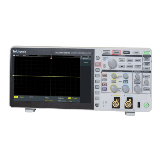
Page 35: Getting Acquainted With The Oscilloscope
3. Push the front panel Power button. To power off the oscilloscope on: cord: 1. Push the front panel Power button. 2. Disconnect the power cord from the main source and the oscilloscope power connector. TBS2000B Series Oscilloscopes User Manual... - Page 36 Getting acquainted with the oscilloscope NOTE. The current instrument settings are stored in nonvolatile memory when you power off the oscilloscope. The oscilloscope restores the settings when you power on. TBS2000B Series Oscilloscopes User Manual...
-
Page 37: Changing The User Interface Language
2. Push the Language side-menu button. The oscilloscope opens the Language menu. You will use the Multipurpose knob to select and click menu items. The following text describes how the Multipurpose knob works. TBS2000B Series Oscilloscopes User Manual... - Page 38 Selecting a menu item does not execute (run) that function. ■ Click function, where you push the knob to either run the selected menu item or enable a field in that menu item to enter numbers or select values. TBS2000B Series Oscilloscopes User Manual...
- Page 39 3. Turn the Multipurpose knob to select a language. 4. Push the Multipurpose knob to select the highlighted language. The selected language takes effect immediately. 5. Push the Menu On/Off button to close the Utility menu. TBS2000B Series Oscilloscopes User Manual...
- Page 40 Insert the overlay tabs into the small slots. If you are changing from a non English language to English, remove the front-panel language overlay. TBS2000B Series Oscilloscopes User Manual...
-
Page 41: Changing The Date And Time
These steps also introduce you to more functions of the menu system. 1. Push Utility front-panel button. 2. Push Set Date & Time side-menu button. The oscilloscope shows the Set Date & Time menu. 3. Turn the Multipurpose knob to select the Year field. TBS2000B Series Oscilloscopes User Manual... - Page 42 Multipurpose knob to select Apply, then click the knob to enter the date/ time settings into the oscilloscope. 8. To turn off displaying the date and time, select Display Date & Time and click the Multipurpose knob to toggle On or Off. TBS2000B Series Oscilloscopes User Manual...
- Page 43 Getting acquainted with the oscilloscope 9. Push the Menu On/Off button to close the Utility side menu. The new date and time are shown in the lower-right corner of the screen. TBS2000B Series Oscilloscopes User Manual...
-
Page 44: Connecting Probes To The Oscilloscope
1 MΩ channel input impedance. ® 2. Tektronix Versatile Probe Interface (TekVPI ): Push the probe base into the channel connector until the probe base connector clicks. To remove, push and hold the button on the probe base and pull the probe from the connector. -
Page 45: Supported Probe Types
Getting acquainted with the oscilloscope Supported probe types For more information on the many probes available for use with TBS2000B Series oscilloscopes, visit the Oscilloscope Probe and Accessory Selector tool on the Tektronix Web site (www.tek.com). TBS2000B Series Oscilloscopes User Manual... -
Page 46: Reducing Electrostatic Damage While Taking Measuremens
Perform this quick functional check to verify that your oscilloscope is operating correctly. Connect the oscilloscope power cable as described in Powering On the Oscilloscope. See Powering the oscilloscope on page 13. Power on the oscilloscope. TBS2000B Series Oscilloscopes User Manual... - Page 47 5 V connector, and the ground clip connects to the ground connector. Push Default Setup. Default Setup returns the oscilloscope settings to factory default values. See default oscilloscope settings Default Setup on page 194. Push Autoset. TBS2000B Series Oscilloscopes User Manual...
- Page 48 You can compensate the probe after completing this functional check. See Compensating a passive voltage probe on page 28. Push Measure to open the Measurement Selection menu. Turn the Multipurpose knob to select Snapshot. TBS2000B Series Oscilloscopes User Manual...
-
Page 49: What Is Autosetquery
(displayed) channel. This powerful function can save you time when you need to view an unknown signal. See the Autoset topic for more information. See Using Autoset on page 67. TBS2000B Series Oscilloscopes User Manual... -
Page 50: Compensating A Passive Voltage Probe
To properly compensate your passive probe: 1. Power on the oscilloscope. 2. Connect the probe to an oscilloscope channel. TBS2000B Series Oscilloscopes User Manual... - Page 51 The probe tip connects to the 5 V connector, and the ground clip connects to the ground connector. 4. Push Default Setup. 5. Push the Vertical Menu button for the channel to which the probe is connected, to display that channel. TBS2000B Series Oscilloscopes User Manual...
- Page 52 If the waveform has a square leading edge and a flat top and bottom, the probe does not need adjusted. If the waveform leading edge is rounded or has a spike, you need to adjust the probe compensation. TBS2000B Series Oscilloscopes User Manual...
-
Page 53: Probes And Ground Leads Tip
When taking a real measurement, use the shortest possible ground lead and signal path to minimize Signal with a short length ground Signal with a long ground lead probe-induced lead ringing and distortion on the measured signal. TBS2000B Series Oscilloscopes User Manual... -
Page 54: Signal Path Compensation Spc
SPC is complete. SPC can take several minutes to run, so wait until the oscilloscope shows a message that SPC is completed. 8. Push Menu Off to remove the message and menus. 9. Reconnect probes to the oscilloscope. TBS2000B Series Oscilloscopes User Manual... -
Page 55: Getting On-Screen Help For Settings - Help Everywhere
Help Everywhere is a mode that displays graphics and short text descriptions when you access the menus for most oscilloscope settings. This is very useful for when you are first learning the functions of oscilloscope controls. TBS2000B Series Oscilloscopes User Manual... - Page 56 Everywhere content is set to Off by default except for the Measurement category, which is On. 3. To turn all Help Everywhere content on or off, use the Multipurpose knob to select Set All to On or Set All to Off, then click the knob. TBS2000B Series Oscilloscopes User Manual...
- Page 57 NOTE. You may need to turn the Multipurpose knob and select another menu item to show the Help Everywhere content. When any Help Everywhere content is enabled, the Help Everywhere icon is highlighted (in upper right corner of screen). TBS2000B Series Oscilloscopes User Manual...
-
Page 58: The Scope Intro Function
Intro side-menu button to return to the main menu, and select a new category to read. 7. Push the Menu On/Off button to close the Scope Intro mode. NOTE. The Scope Intro function does not remember which topics you have read. TBS2000B Series Oscilloscopes User Manual... -
Page 59: Oscilloscope Concepts
Each oscilloscope channel has its own waveform record memory storage. TBS2000B Series oscilloscopes use real-time sampling. In real-time sampling, the oscilloscope samples and digitizes all of the sampled points at one time, in sequence, stores the sampled data in memory, and then repeats the sampling and storage process. - Page 60 How the values in the acquisition interval are used is set by the acquisition mode. TBS2000B Series Oscilloscopes User Manual...
-
Page 61: Acquisition Mode Concepts
Use Hi Res mode to provide higher- resolution (16-bit) sample points for lower-frequency waveforms. Average mode calculates and displays the average value for each sample point over a user-specified number of acquisitions. Use Average mode to reduce random noise. TBS2000B Series Oscilloscopes User Manual... -
Page 62: Trigger Concepts
When displayed, the waveform record for each acquisition shows the waveform at the same trigger point, resulting in a stable waveform on the screen. TBS2000B Series Oscilloscopes User Manual... - Page 63 By analyzing what happens before the glitch, you may uncover information that helps you find the source of the glitch. TBS2000B Series Oscilloscopes User Manual...
-
Page 64: Trigger Slope And Level Concepts
The trigger Slope sets the oscilloscope to find the trigger event on the rising or the falling edge of a signal. The trigger threshold Level (or just level) is the signal amplitude value on a slope that must occur for the oscilloscope to trigger on a signal. TBS2000B Series Oscilloscopes User Manual... - Page 65 Turning the Trigger Level knob changes the threshold level and momentarily displays a long horizontal line (or two lines for a runt trigger) across the waveform to show the trigger level(s) in relation to the overall waveform. TBS2000B Series Oscilloscopes User Manual...
-
Page 66: Available Trigger Types
(or either) runt signal. You can also trigger on runt signals with pulse widths that are less than, greater than, equal to, or not equal to a specified width. Runt triggers are primarily used to analyze digital signals. TBS2000B Series Oscilloscopes User Manual... -
Page 67: Trigger Coupling
Auto mode, when forcing triggers in the absence of valid triggering events, does not synchronize the waveform on the display. The waveform will appear to roll across the screen. If valid triggers occur, the display will become stable. TBS2000B Series Oscilloscopes User Manual... -
Page 68: Normal Trigger Mode
For example, you can trigger on a pulse that occurs once every 10 ms and then use Delay to look at the signal characteristics that occur 6 ms after the trigger point. TBS2000B Series Oscilloscopes User Manual... -
Page 69: Setting Channel Input Parameters
2. Push the Coupling side-menu button. 3. Use the Multipurpose knob to select and click the coupling type: DC coupling passes both AC and DC signal components. AC coupling blocks the DC component and passes only the AC signal. TBS2000B Series Oscilloscopes User Manual... -
Page 70: Inverting The Input Signal
1. Push the Vertical Menu button for the channel input that you want to set. 2. Push the Invert side-menu button to toggle between Off for normal operation and On to invert the polarity of the signal in the preamplifier. TBS2000B Series Oscilloscopes User Manual... -
Page 71: Setting The Oscilloscope Bandwidth
Full sets the bandwidth to the maximum bandwidth of which the oscilloscope is capable. ■ 20 MHz sets the bandwidth to 20 MHz. ■ Other bandwidth choices may be shown on the menu depending on the connected probe. TBS2000B Series Oscilloscopes User Manual... -
Page 72: Setting The Probe Type Voltage Or Current
2. Push the Probe Setup side menu to display the Probe Setup submenu. 3. Use the Multipurpose knob to select and click Probe Type submenu item. 4. Select and click the probe type (Voltage or Current). TBS2000B Series Oscilloscopes User Manual... -
Page 73: Setting The Probe Attenuation Factor
2. Push the Probe Setup side menu to display the Probe Setup submenu. 3. Use the Multipurpose knob to select and click the Attenuation submenu item. 4. Use the Multipurpose knob to select and change the attenuation factor. TBS2000B Series Oscilloscopes User Manual... -
Page 74: Quickly Setting The Probe Attenuation To 1X Or 10X
2. Push the Probe Setup side menu to display the Probe Setup submenu. 3. Use the Multipurpose knob to highlight either Set To 1X or Set To 10X submenu item. Then click the Multipurpose knob to set that value. TBS2000B Series Oscilloscopes User Manual... -
Page 75: Setting The Measure Current Mode For Voltage Probes
4. Push the Multipurpose knob to toggle between Yes and No. 5. If you select Yes, the area below the Measure Current submenu displays the Amps/Volts or Volts/Amps ratio menu item. Use the Multipurpose knob to select and change the current measurement parameter. TBS2000B Series Oscilloscopes User Manual... -
Page 76: Setting The Input Signal Vertical Offset
Click the knob again to exit the field. 4. To set the offset value to 0, use the Multipurpose knob to select and click Set to 0. TBS2000B Series Oscilloscopes User Manual... -
Page 77: Setting The Waveform Vertical Position
Click the knob again to exit the field. 5. To set the position to 0 (center graticule), use the Multipurpose knob to select and click Set to 0. TBS2000B Series Oscilloscopes User Manual... -
Page 78: The Difference Between Vertical Position And Vertical Offset
Vertical Position knob to move the peak area to the center graticule, and then set the Vertical Scale knob to smaller voltage/division settings to look at more detail in that waveform peak area. TBS2000B Series Oscilloscopes User Manual... -
Page 79: Setting Channel Deskew
4. To set a specific deskew delay, use the Multipurpose knob to select and click 0s. Then use the knob to change and set the value. The waveform on the screen moves as you adjust the value. TBS2000B Series Oscilloscopes User Manual... -
Page 80: Deskew Tips
Deskew settings are stored in nonvolatile memory until changed manually for each channel. ■ Deskew settings are included in saved setup files. ■ Doing a Default Setup resets deskew values to 0 on all channels. TBS2000B Series Oscilloscopes User Manual... -
Page 81: Trigger Setup
Trigger setup Use these procedures to set up the oscilloscope to trigger on a signal. See Trigger concepts on page 40. TBS2000B Series Oscilloscopes User Manual... -
Page 82: Triggering On A Waveform Edge
5. Push the Coupling side-menu button and use the Multipurpose knob to select and click the trigger coupling. See Trigger coupling on page 45. 6. Push the Slope side-menu button to select between rising and falling slope edges on which to trigger the oscilloscope. TBS2000B Series Oscilloscopes User Manual... - Page 83 (or two lines for a runt trigger) across the waveform to show the trigger level(s) in relation to the waveform. Push the Trigger Level knob to immediately set the trigger to 50% of the signal peak-to-peak level. TBS2000B Series Oscilloscopes User Manual...
-
Page 84: Triggering On A Specified Pulse Width
7. Push the Trigger When side-menu button and use the Multipurpose knob to select and click the pulse width condition on which to trigger. Then use the Multipurpose knob to enter the pulse width time parameter. TBS2000B Series Oscilloscopes User Manual... -
Page 85: Triggering On A Runt Pulse
ECL, and so on) or to 0. 7. Push the Trigger When side-menu button and use the Multipurpose knob to select and click Runt Occurs to trigger on any runt event. If triggering on a TBS2000B Series Oscilloscopes User Manual... - Page 86 Trigger setup runt width, use the Multipurpose knob to select and click the runt pulse width condition to test for, and enter the runt width time parameter. TBS2000B Series Oscilloscopes User Manual...
-
Page 87: Setting The Trigger Mode
Click Holdoff to set a time period after a trigger event, during which the oscilloscope ignores new trigger events. Once the holdoff period is over, the oscilloscope starts looking for the trigger condition. The minimum holdoff period is 20 ns. See Holdoff trigger mode on page 46. TBS2000B Series Oscilloscopes User Manual... - Page 88 Trigger setup TBS2000B Series Oscilloscopes User Manual...
-
Page 89: Acquisition Setup
50% of the signal level, and analyzes the input signal and adjusts the oscilloscope acquisition, horizontal, and vertical settings to display five to six waveform cycles. Autoset is ideal for quickly displaying a repeating signal waveform. TBS2000B Series Oscilloscopes User Manual... - Page 90 2. Push the Vertical Menu button for the channel input that you want to Autoset, to enable that channel. 3. Push Autoset. The oscilloscope takes a few moments to analyze and display the signal. 4. You can push the Undo Autoset side-menu button to undo the last Autoset. TBS2000B Series Oscilloscopes User Manual...
-
Page 91: Autoset Tips
1 even if no signal is present (resulting in a flat waveform for channel 1). It will not trigger on, or display the other channels, even if there are signals present on those channels. TBS2000B Series Oscilloscopes User Manual... -
Page 92: How To Enable/Disable Autoset In The Oscilloscope
Use this procedure to enable/disable the Autoset function to set up a waveform manually. NOTE. To disable or enable the Autoset function requires a password. The default factory password is 000000. 1. Push Utility. 2. Push -More- Page 1/2 side-menu button. 3. Push Feature Enable side-menu button. TBS2000B Series Oscilloscopes User Manual... -
Page 93: How To Change The Autoset Password
Autoset mode. 1. Push Utility. 2. Push -More- Page 1/2 side-menu button. 3. Push Feature Enable side-menu button. 4. Use the Multipurpose knob to select and click Autoset Enable. TBS2000B Series Oscilloscopes User Manual... - Page 94 Then push the OK side-menu button. Reenter the new password to confirm it and push the OK side-menu button. NOTE. The Autoset enable/disable can be done using the PI commands. Refer Programmer manual for detailed instructions. TBS2000B Series Oscilloscopes User Manual...
-
Page 95: Starting And Stopping An Acquisition
Single button. ■ Push Single to take a single acquisition. Single sets the trigger mode to Normal for the single acquisition. TBS2000B Series Oscilloscopes User Manual... -
Page 96: Setting The Acquisition Mode
3. Turn the Multipurpose knob to select a mode (Sample, Peak Detect, Hi res, Average), then click the Multipurpose knob to enable that mode. 4. If you select Average, use the Multipurpose knob to select of how many acquisitions to average to create the waveform. TBS2000B Series Oscilloscopes User Manual... -
Page 97: Setting The Acquisition Trigger Delay Time
2. Push the Delay side-menu button to toggle between On and Off. When set to Off, the expansion point is tied to the trigger point so that horizontal scale changes are centered around the trigger point. TBS2000B Series Oscilloscopes User Manual... - Page 98 You can also push the front-panel Horizontal Position knob to return the trigger point to the center of the waveform record. Trigger Delay is different than Trigger Holdoff. See Holdoff trigger mode page 46. TBS2000B Series Oscilloscopes User Manual...
-
Page 99: Setting The Record Length
3. Use the Multipurpose knob to select and set the record length. Use longer record lengths to either capture more samples for a waveform record, or capture more cycles of a waveform, then use the Zoom controls to investigate the waveform in more detail. TBS2000B Series Oscilloscopes User Manual... -
Page 100: Using The Roll Display Mode
Auto and the horizontal scale and record lengths are set as follows: Table 5: Roll mode is enabled when: Horizontal scale setting Record length (number of samples) 40 ms/div 1000, 2000, 20k, 200k, 2M 400 ms/div TBS2000B Series Oscilloscopes User Manual... -
Page 101: Roll Mode Tips
When horizontal scale is set to 40 ms/division or higher (for 5 M record lengths, this is limited to 400 ms/division or higher) NOTE. The Average acquisition mode is unavailable when you are using Roll mode. TBS2000B Series Oscilloscopes User Manual... -
Page 102: Setting The Oscilloscope To Factory Default Values - Default Setup
2. If you change your mind, push Undo Default Setup side-menu button to return the oscilloscope to the settings present before you pushed Default Setup. You must push this button before doing any other action. TBS2000B Series Oscilloscopes User Manual... -
Page 103: Waveform Display Settings
If the channel is not active, pushing the channel Menu button selects that channel; another push removes the waveform from the screen. If more than one waveform is displayed on the screen, selecting a channel draws the corresponding waveform on top of all other waveforms. TBS2000B Series Oscilloscopes User Manual... -
Page 104: Setting The Waveform Persistence
Auto, that gives the best performance. 5. To clear the persistence of the displayed waveform, select and click Clear Persistence. This does not change the persistence setting, but just clears the displayed waveform persistence data. TBS2000B Series Oscilloscopes User Manual... -
Page 105: Waveform Persistence Tip
Waveform display settings Waveform persistence tip To quickly clear the displayed waveform persistence data, push Single, then push Run/Stop to restart active waveform acquisition. TBS2000B Series Oscilloscopes User Manual... -
Page 106: The Xy Display Mode
2 (Y), where channel 1 is the horizontal axis and channel 2 is the vertical axis. XY display mode is useful for showing signal phase or frequency relationships between periodic signals. The resulting XY plots are called Lissajou patterns. TBS2000B Series Oscilloscopes User Manual... - Page 107 1. Select the two signal sources that you want to plot. Push the Vertical Position knob for each channel to set the ground reference of both signals to 0 V (center horizontal graticule) so that the XY plot is centered on the screen. 2. Push Acquire. TBS2000B Series Oscilloscopes User Manual...
-
Page 108: Xy Display Mode Tips
USB drive for off-line analysis. Use a Web browser and search on the keyword “lissajou patterns” to find ■ more information on XY plots. TBS2000B Series Oscilloscopes User Manual... -
Page 109: Setting The Backlight Intensity
1. Push Utility. 2. Push the Display side-menu button. 3. Use the Multipurpose knob to select and click Backlight Intensity. 4. Use the Multipurpose knob to change and set the backlight value. TBS2000B Series Oscilloscopes User Manual... - Page 110 Waveform display settings TBS2000B Series Oscilloscopes User Manual...
-
Page 111: Analyzing A Waveform
5. Measurements with a down triangle contain a list of the input channels to use for that measurement when selected. Select and click the input channels. Then push the Menu On/Off button to close the list. TBS2000B Series Oscilloscopes User Manual... -
Page 112: Automatic Measurements Tip
Wait for measurement module to get proper measurement. As soon as the proper measurement is available, the symbol will disappear. TBS2000B Series Oscilloscopes User Manual... -
Page 113: Taking A Measurement Snapshot
See Saving files to USB with the Save File button on page 133. 6. Push the Menu On/Off button to close the Snapshot screen and return to the measurements menu. TBS2000B Series Oscilloscopes User Manual... -
Page 114: Snapshot Measurement Tip
The following tables list the automatic measurements, grouped as shown on the measurements menu. Measurement descriptions can also be shown on the oscilloscope by enabling Help Everywhere (Help > Help Everywhere). See Getting on-screen help for settings - Help Everywhere on page 33. Frequency measurement descriptions TBS2000B Series Oscilloscopes User Manual... - Page 115 –Edges The number of negative transitions from the high reference value to the low reference value in the waveform or gated region. TBS2000B Series Oscilloscopes User Manual...
-
Page 116: Time Measurement Descriptions
DelayRR The time between the mid reference (default 50%) amplitude point of the rising edge of two different waveforms. See also Phase. This measurement requires inputs from two channels. TBS2000B Series Oscilloscopes User Manual... - Page 117 –Width Negative pulse width. The distance (time) between the mid reference (default 50%) amplitude points of a negative pulse. The measurement is made on the first pulse in the waveform or gated region. TBS2000B Series Oscilloscopes User Manual...
-
Page 118: Amplitude Measurement Descriptions
Amplitude The average high value less the average low value measured over the entire waveform or gated region. The most positive peak voltage. Max is measured over the entire waveform or gated region. TBS2000B Series Oscilloscopes User Manual... - Page 119 This is measured over the entire waveform or gated region and is expressed as: Negative Overshoot = (Low – Minimum) / Amplitude x 100%. Mean The arithmetic mean over the entire waveform or gated region. TBS2000B Series Oscilloscopes User Manual...
-
Page 120: Area Measurement Descriptions
The area above the common reference point is positive, and the area below the common reference point is negative. TBS2000B Series Oscilloscopes User Manual... -
Page 121: Taking A Measurement On Just A Part Of The Waveform Gating
(Off (Full Record), Screen, Between Cursors) If selecting Between Cursors, use the Multipurpose knob to select and move the gating cursors to mark the waveform area to use for automatic measurements. TBS2000B Series Oscilloscopes User Manual... -
Page 122: How To Enable / Disable Measurement In The Oscilloscope
4. Use the Multipurpose knob to select and click Measurement Enable. The oscilloscope opens the Feature Enable password entry screen. 5. Use the Multipurpose knob and side-menu buttons to enter the password that lets you disable Measurement. TBS2000B Series Oscilloscopes User Manual... -
Page 123: How To Change The Measurement Password
4. Use the Multipurpose knob to select and click Change Password. The oscilloscope opens the Change Password entry screen. 5. Use the Multipurpose knob and side-menu buttons to select the alphanumeric and enter characters for the current password. 6. Push OK side-menu button. TBS2000B Series Oscilloscopes User Manual... - Page 124 7. Use the Multipurpose knob and side-menu buttons to enter the new password to confirm it. 8. Push OK side-menu button. NOTE. The measurement password can be changed using the PI commands. Refer to Programmer manual for detailed instructions. TBS2000B Series Oscilloscopes User Manual...
-
Page 125: Using Cursors To Take Manual Measurements
NOTE. Cursors are not available in XY display mode. 1. Push Cursors to display two vertical Time cursors by default. The color of the cursors indicates the channel on which they are taking measurements. TBS2000B Series Oscilloscopes User Manual... - Page 126 See Cursor types on page 106. 6. Push the Link side-menu button to turn cursor linking On or Off. If linking is On, turning the Multipurpose knob moves both cursors at the same time. TBS2000B Series Oscilloscopes User Manual...
- Page 127 7. If one or both of the cursors are off of the screen, push the Bring Cursor On Screen side-menu button to bring off-screen cursors back to the screen. 8. Push the Cursors front panel button to turn the cursors off. TBS2000B Series Oscilloscopes User Manual...
-
Page 128: Cursor Types
NOTE. The vertical cursors in screen mode are not tied to where the cursor crosses the waveform, and so do not show the amplitude value where they cross the signal. Amplitude values are read from the horizontal cursors. TBS2000B Series Oscilloscopes User Manual... -
Page 129: How To Enable / Disable Cursor In The Oscilloscope
1. Push Utility. 2. Push -More- Page 1/2 side-menu button. 3. Push Feature Enable side-menu button. 4. Use the Multipurpose knob to select and click Cursor Enable. The oscilloscope opens the Feature Enable password entry screen. TBS2000B Series Oscilloscopes User Manual... -
Page 130: How To Change The Cursor Password
4. Use the Multipurpose knob to select and click Change Password. The oscilloscope opens the Change Password entry screen. 5. Use the Multipurpose knob and side-menu buttons to select the alphanumeric and enter characters for the current password. 6. Push OK side-menu button. TBS2000B Series Oscilloscopes User Manual... - Page 131 7. Use the Multipurpose knob and side-menu buttons to enter the new password to confirm it. 8. Push OK side-menu button. NOTE. The cursor password can be changed using the PI commands. Refer to Programmer manual for detailed instructions. TBS2000B Series Oscilloscopes User Manual...
-
Page 132: Creating Math Waveforms
9. To change the size (vertical scale) of the math waveform, push the Vertical Scale side-menu button and use the Multipurpose knob to change the waveform scale. Note that the math vertical scale setting only applies to the math waveform. TBS2000B Series Oscilloscopes User Manual... -
Page 133: Math Waveform Tips
You can also recall (load) math waveforms into reference memory. See Recalling waveform data on page 136. You can zoom in on math waveforms using the Navigation controls (Zoom ■ button and Multipurpose knob). TBS2000B Series Oscilloscopes User Manual... -
Page 134: Using Fft To See Signal Frequency Information
In other words, an FFT is a basic spectrum analyzer function to analyze frequency components of a waveform. 1. Acquire and display several cycles of the waveform. NOTE. You can only display FFT waveforms for 2000 and 20K point record length waveforms. 2. Push FFT button. TBS2000B Series Oscilloscopes User Manual... - Page 135 5. Push the Vertical Units side-menu button and use the Multipurpose knob to select and click dBV RMS or Linear RMS. Use the default dBV RMSVertical Units scale to see a detailed view of multiple frequencies, even if the frequencies have very different amplitudes. TBS2000B Series Oscilloscopes User Manual...
- Page 136 Multipurpose knob to position the FFT graph horizontally. The readout on the side menu is the frequency of the waveform point that is positioned on the center vertical graticule. Use this to quickly measure FFT ‘spike’ frequencies. TBS2000B Series Oscilloscopes User Manual...
- Page 137 FFT waveform to show more or less detail. The FFT waveform expands around the center cursor. 9. Push the Cursors front-panel button and use the cursors to take measurements. TBS2000B Series Oscilloscopes User Manual...
-
Page 138: Fft Tips
Using a window on the source signal results in an FFT waveform that more accurately represents the source signal frequency components. TBS2000B Series Oscilloscopes User Manual... - Page 139 What you want to measure, and your source signal characteristics, help you to select which window to use. Use the following guidelines to select the best window for your signal analysis needs. The Hanning window is a good starting point for FFT measurements. TBS2000B Series Oscilloscopes User Manual...
- Page 140 Blackman-Harris This is the best window for measuring the amplitude of frequencies but worst at resolving frequencies. Use Blackman-Harris for measuring predominantly single frequency waveforms to look for higher order harmonics. TBS2000B Series Oscilloscopes User Manual...
-
Page 141: Fft And Display Waveform Aliasing
Use a filter on the input signal to limit the signal to frequencies below that of the Nyquist frequency. If the frequency components you are interested in are below the built-in 20 MHz bandwidth setting, push the Vertical Menu button and set the channel bandwidth to 20 MHz. TBS2000B Series Oscilloscopes User Manual... -
Page 142: Displaying Reference Waveforms
You can use Zoom to show more detail on reference waveforms. ■ TBS2000B Series Oscilloscopes User Manual... -
Page 143: How To View Long Record Length Waveforms Zoom
3. Push the Scale side-menu button and use the Multipurpose knob to adjust the size of the area to zoom (magnify). 4. Push the Position side-menu button and use the Multipurpose knob to adjust the position of the zoom area in the waveform record. TBS2000B Series Oscilloscopes User Manual... -
Page 144: How To Search And Mark A Waveform
4. Delete a mark. Push the next ( →) or previous (←) arrow button to jump to the mark you want to clear. To remove the current, center-positioned mark, push Set/Clear. It works on both manually and automatically created marks. TBS2000B Series Oscilloscopes User Manual... - Page 145 Analyzing a waveform To automatically set and clear (delete) search marks: 1. Push Search. 2. Push the Search lower side-menu button and select On. The search menu is similar to the trigger menu. 3. Push Search Type. TBS2000B Series Oscilloscopes User Manual...
- Page 146 Automatic search marks are not saved with the waveform when the ■ waveform is saved. However, you can easily recapture them by reusing the search function. The search criteria are saved in the saved setup. ■ TBS2000B Series Oscilloscopes User Manual...
-
Page 147: How To Pan A Waveform
To pan a waveform, turn the Multipurpose knob when the side-menu button of Position is selected in the Zoom menu. Turn the Multipurpose knob clockwise to pan forward. Turn it counterclockwise to pan backwards. The further you turn the knob, the faster the zoom window pans. TBS2000B Series Oscilloscopes User Manual... - Page 148 Analyzing a waveform TBS2000B Series Oscilloscopes User Manual...
-
Page 149: Feature Enable
For further details refer to How to enable / disable cursor in the oscilloscope page 107. Disable measurement in the oscilloscope For further details refer to How to enable / disable measurement in the oscilloscope on page 100. TBS2000B Series Oscilloscopes User Manual... - Page 150 Feature enable TBS2000B Series Oscilloscopes User Manual...
-
Page 151: Saving Data
7. Select and click a graphical file format (BMP, JPG, or PNG). 8. Push the Save side-menu button to save the screen image to an automatically-named file at the top level of the USB drive. About automatically generated file names on page 146. TBS2000B Series Oscilloscopes User Manual... -
Page 152: About Saved Image File Formats
4. Push the Action side-menu button. 5. Use the Multipurpose knob to select and click Save Waveform. 6. To save waveform data to internal reference memory: a. Push the Save To side-menu button. b. Select and click Ref. TBS2000B Series Oscilloscopes User Manual... -
Page 153: About Waveform Data Files
ISF file, and takes longer to write to the USB drive. To find out the channel for which the file was written, open the file in a text ■ editor. The channel name is in the top few lines of the file. TBS2000B Series Oscilloscopes User Manual... -
Page 154: Saving Oscilloscope Setup Information
Use the Multipurpose knob to select and click USB File (*.SET file). c. Push Save TEKxxxxx.SET side-menu button to save the setup data to an automatically named *.SET file at the top level of the USB drive. See About automatically generated file names on page 146. TBS2000B Series Oscilloscopes User Manual... -
Page 155: Saving Files To Usb With The Save File Button
4. For image or setup files: Use the Save/Rec side-menu buttons to select the output format for the action you assigned to the Save button (BMP, JPG, or PNG for screen images; .ISF or .CSV for waveforms). NOTE. Setup files will always be saved as .SET files. TBS2000B Series Oscilloscopes User Manual... - Page 156 USB drive. NOTE. The Assign To button does not store the current save settings (such as file format or waveform source). The Save button uses the settings of the Save/Rec side menu to save files. TBS2000B Series Oscilloscopes User Manual...
-
Page 157: Recalling Data
3. Push the Action side-menu button. 4. Use the Multipurpose knob to select and click Recall Setup. 5. To recall setup data from internal setup memory: a. Push the Recall From side-menu button. b. Select and click Setup. TBS2000B Series Oscilloscopes User Manual... -
Page 158: Recalling Waveform Data
5. Push the To side-menu button. 6. Select and click Ref1 or Ref2. 7. Push Select File side-menu button to open the File Utility pane. 8. Use the Multipurpose knob to select the waveform file (*.ISF). TBS2000B Series Oscilloscopes User Manual... - Page 159 Recalling data 9. Push Recall side-menu button. The oscilloscope loads the waveform data into the selected reference memory. NOTE. If the Recall side-menu button shows No file, then you have not selected an .ISF file. TBS2000B Series Oscilloscopes User Manual...
- Page 160 Recalling data TBS2000B Series Oscilloscopes User Manual...
-
Page 161: Using The Usb File Utility Functions
The area below the Directory field shows the files and folders. Use the Multipurpose knob to highlight a name. Push the Multipurpose to open or close a folder. Folders are marked with a ► when closed, and with a ▼ when that folder is open. TBS2000B Series Oscilloscopes User Manual... - Page 162 Use the lower side-menu buttons to show upper-or lower-case letters on the keyboard or show a numeric keypad. ■ Push the OK side-menu button to create or rename the file or folder with the name in the Directory field. TBS2000B Series Oscilloscopes User Manual...
-
Page 163: Changing The Default File Save Location On The Usb Drive
Use the Change Folder function to change the working folder location to an existing folder and try the save operation again. Deleting the save location folder. ■ Removing or inserting a USB drive. ■ Pushing the Default Setup front-panel button. ■ TBS2000B Series Oscilloscopes User Manual... -
Page 164: Creating A New Folder On The Usb Drive
MyProject1-4). These names will change to show the most recent file or folder names that you have created. These names change back to the default values when you power off the oscilloscope or push the Default Setup front-panel button. TBS2000B Series Oscilloscopes User Manual... -
Page 165: Folder Creation Tip
If you have critical or secure data that must be removed from the USB drive, connect the USB drive to a PC and use a file ‘shredding’ program to replace the file data with zeros. TBS2000B Series Oscilloscopes User Manual... -
Page 166: Renaming Files Or Folders On The Usb Drive
7. Push the OK side-menu button to add the new folder name to the USB drive. NOTE. You do not need to add the file extension name (.ISF, .SET, and so on) when renaming an image, waveform, or setting file. TBS2000B Series Oscilloscopes User Manual... -
Page 167: File Folder Renaming Tip
1. Push the Save/Recall front-panel button. 2. Push the File Utility side-menu button. 3. Push the Format side-menu button. 4. Use the Multipurpose knob to select and click Yes. The oscilloscope formats the drive and reopens the file utility pane. TBS2000B Series Oscilloscopes User Manual... -
Page 168: About Automatically Generated File Names
To determine the channel or waveform type (Math, FFT, Ref) of a saved ■ waveform file, open the waveform file (.CSV or .ISF) in a text editor. The channel name or waveform type is at or near the top of the file structure. TBS2000B Series Oscilloscopes User Manual... -
Page 169: Erasing Data From Oscilloscope Memory (Teksecure)
6. To cancel the procedure, select No or push the Menu Off button. 7. When the TekSecure procedure is finished, the oscilloscope automatically powers off and then powers back on. TBS2000B Series Oscilloscopes User Manual... - Page 170 Erasing data from oscilloscope memory (TekSecure) TBS2000B Series Oscilloscopes User Manual...
-
Page 171: Setting Or Viewing Usb Device Port Parameters
A grayed out menu item cannot be selected. 4. If the USB Device port is Disabled (off Bus), select and click the device to which you want to connect. TBS2000B Series Oscilloscopes User Manual... -
Page 172: Disabling The Usb Device Port
USB devices to communicate using IEEE488 style messages. This protocol lets you run your GPIB software applications on USB hardware. Use this screen to view protocol registration information. There are no active controls on this screen. 1. Push Utility front-panel button. TBS2000B Series Oscilloscopes User Manual... - Page 173 Setting or viewing USB Device port parameters 2. Push the Config side-menu button. 3. Use the Multipurpose knob to select and click USB. 4. Select and click USBTMC Configuration. The oscilloscope shows the USBTMC protocol registration information. TBS2000B Series Oscilloscopes User Manual...
- Page 174 Setting or viewing USB Device port parameters TBS2000B Series Oscilloscopes User Manual...
-
Page 175: Setting Up The Lan Network
4. Select and click LAN Settings. The oscilloscope shows the IP address and other network-related settings. If no IP address information is shown, and you need to set up the oscilloscope for network access, work with your network administrator to determine how to get an IP address. TBS2000B Series Oscilloscopes User Manual... -
Page 176: Setting The Ip Address Dhcp Network- Ethernet
A Dynamic Host Configuration Protocol (DHCP) network automatically allocates network IP addresses and settings to DHCP-enabled instruments like the TBS2000B Series oscilloscope. Use this procedure to turn DHCP-capability on and enable the oscilloscope to obtain an IP address from the network DHCP server. -
Page 177: Setting The Ip Address Nondhcp Network- Ethernet
(white). NOTE. If the LAN Test menu item shows No Response, work with your system administrator to confirm that the settings that you were given are correct. Check that you entered the settings correctly. TBS2000B Series Oscilloscopes User Manual... -
Page 178: Turning Ethernet Dhcp On Or Off
Turning Ethernet DHCP on or off A Dynamic Host Configuration Protocol (DHCP) network automatically allocates network IP addresses and settings to DHCP-enabled instruments like the TBS2000B Series oscilloscope. Use this procedure to turn the oscilloscope DHCP-capability on or off. 1. Push Utility front-panel button. -
Page 179: Setting Up The Wi-Fi Network
Use this procedure to turn on or off Wi-Fi. Prerequisites: ■ Connect a supported Wi-Fi dongle to the rear USB Host port (Tektronix option TEKUSBWIFI). Recommendation is to use the rear USB port so that you keep the front USB port available for saving and loading files. -
Page 180: Viewing Wi-Fi Settings
Prerequisite: A Wi-Fi dongle is connected to the oscilloscope and Wi-Fi is turned on. See Turning Wi-Fi on or off on page 157. 1. Push the Utility front-panel button. 2. Push the Config side-menu button. TBS2000B Series Oscilloscopes User Manual... -
Page 181: Setting The Ip Address (Nondhcp) Network In Wi-Fi
(white). NOTE. If the LAN Test menu item shows No Response, work with your system administrator to confirm that the settings that you were given are correct. Check that you entered the settings correctly. TBS2000B Series Oscilloscopes User Manual... -
Page 182: Setting The Ip Address Dhcp Network In Wi-Fi
A Dynamic Host Configuration Protocol (DHCP) network automatically allocates network IP addresses and settings to DHCP-enabled instruments like the TBS2000B Series oscilloscope. Use this procedure to turn DHCP-capability on and enable the oscilloscope to obtain an IP address from the network DHCP server. -
Page 183: Turning Dhcp On Or Off Wi-Fi
Turning DHCP on or off Wi-Fi A Dynamic Host Configuration Protocol (DHCP) network automatically allocates network IP addresses and settings to DHCP-enabled instruments like the TBS2000B Series oscilloscope. Use this procedure to turn the oscilloscope DHCP-capability on or off. Prerequisites: ■... - Page 184 Setting up the Wi-Fi network TBS2000B Series Oscilloscopes User Manual...
-
Page 185: Connecting Your Oscilloscope To A Computer
There are two ways to connect your oscilloscope to a computer: ■ VISA drivers. Use VISA to communicate with your oscilloscope from your computer through a software application, such as Tektronix OpenChoice ® Desktop ■... - Page 186 Programmer Manual that is available at the Tektronix website. NOTE. Do not use the backspace key on the computer during an MS Windows Telnet session with the oscilloscope. TBS2000B Series Oscilloscopes User Manual...
-
Page 187: Appendices
4. Use the mouse and cursor to select browser tabs and interact with the available oscilloscope controls. You can use the mouse to select and open menus and submenus. Use the keyboard to enter numeric values where required. NOTE. Search mark feature is not available on the e*Scope. TBS2000B Series Oscilloscopes User Manual... -
Page 188: Installing New Firmware On The Oscilloscope
Appendices Installing new firmware on the oscilloscope Tektronix releases new oscilloscope firmware to improve existing functions or add new functions. Complete the following steps to install new firmware in the oscilloscope. 1. Go to http://tek.com. 2. Click Downloads. In the Downloads menu, select DOWNLOAD TYPE as Software and enter TBS2000B in the MODEL OR KEYBOARD field ad click SEARCH. -
Page 189: Running Diagnostic Tests
1. Push the Utility button. 2. Push the -More- Page 1/2 side-menu button. 3. Push the Diagnostics side-menu button. 4. Push the Self Test side-menu button to display the Self Test menu and Self Test Results readout. TBS2000B Series Oscilloscopes User Manual... -
Page 190: Courseware On-Instrument Education And Training
NOTE. TekSmartLab uses wireless connectivity to connect multiple oscilloscopes and other test bench instruments to a central server and software interface. Using The TBS2000B series oscilloscope with TekSmartLab requires either a Wi- Fi Transceiver USB dongle (Option TEKUSBWIFI) or a communication box to connect to the TekSmartLab server. -
Page 191: Courseware File Content Information
Refer to the Courseware and TekSmartLab documentation for more ■ information on these applications. You can download electronic versions of these manuals from the Tektronix Web site (www.tek.com). Loading a courseware file Use this procedure to load a Courseware file. A Courseware file can have up to 12 courses. -
Page 192: Dealing With Error Message
Prerequisite: You have loaded a course on the oscilloscope. 1. Push the Help front-panel button. TBS2000B Series Oscilloscopes User Manual... - Page 193 USB drive. Make sure to save results to a report 6. Save lab results to a report file on the USB drive. See Saving Courseware lab results on page 172. TBS2000B Series Oscilloscopes User Manual...
-
Page 194: Saving Courseware Lab Results
Figure 3: Navigation on 2 and 4 channel on TBS2000B ■ The Multipurpose knob lets you select and click menu or other choices, to move a cursor, and to set a numerical parameter values for a menu item. TBS2000B Series Oscilloscopes User Manual... - Page 195 (solid line). Push the Multipurpose knob to change the active cursor. Using cursors to take manual measurements on page 103. ■ The Fine button enables making fine adjustments with the Multipurpose knob, vertical and horizontal Position knobs, vertical Scale knob, and the trigger Level knob. TBS2000B Series Oscilloscopes User Manual...
-
Page 196: The Horizontal Controls
Figure 4: Navigation on 2 and 4 channel on TBS2000B The Horizontal controls The Horizontal Position knob adjusts the trigger point location left or right relative to the acquired waveform record. TBS2000B Series Oscilloscopes User Manual... -
Page 197: The Trigger Controls
The Trigger Level knob adjusts the trigger level. Trigger level is shown with a horizontal line when using this control. Push the Trigger Level knob to set the trigger level to 50% (the vertical midpoint of the waveform). The Force Trig button forces an immediate trigger event. TBS2000B Series Oscilloscopes User Manual... -
Page 198: The Vertical Controls
Recalling waveform data on page 136. The FFT button opens the FFT screen and shows side menu where you can ■ set the FFT display parameters. See Using FFT to see signal frequency information on page 112. TBS2000B Series Oscilloscopes User Manual... -
Page 199: The Resources Controls
Ethernet), load new oscilloscope software, and so on. The Utility button also provides controls to access and manage files on a connected USB drive. See Using the USB file utility functions on page 139. Other front-panel controls TBS2000B Series Oscilloscopes User Manual... - Page 200 Appendices The Help button opens a side menu where you can access the Tektronix ■ Courseware lab exercise functions See Courseware on-instrument education and training on page 168 and Help Everywhere on-screen settings and measurements help (See Getting on-screen help for settings - Help Everywhere on page 33.)
-
Page 201: Using The Menu System
Appendices Using the menu system This topic introduces you to the TBS2000B menu system. 1. Push a front-panel menu button to display the menu that you want to use. TBS2000B Series Oscilloscopes User Manual... - Page 202 2. Push a side-menu button to select the on-screen menu item that is next to that button. 3. If the selected side menu item opens another menu, use the Multipurpose knob to highlight an item in the pop-out menu. TBS2000B Series Oscilloscopes User Manual...
- Page 203 7. Push Fine to turn off or on the ability to make smaller adjustments with the Multipurpose knob. Fine works with the Multipurpose knob, Horizontal and Vertical Position knobs, Vertical Scale knob, and the Trigger Level knob. The following topics provide hands-on experience with using the menu system: TBS2000B Series Oscilloscopes User Manual...
-
Page 204: Front-Panel Connectors
2. PROBE COMP. A square wave signal source and ground connection used to compensate probes. Output voltage: ~ 5 V at ~1 kHz Ground reference to which to connect the probe ground lead. Compensating a passive voltage probe on page 28. 3. USB 2.0 Host port. TBS2000B Series Oscilloscopes User Manual... -
Page 205: Rear-Panel Connectors
3. USB 2.0 Host port. A standard USB host port which lets you connect a USB Wi-Fi transceiver adapter (dongle) for wireless connectivity (A Tektronix TBS2000B series exclusive feature), or to USB flash drives with which to save or recall waveforms, settings, screen images, and Courseware education packages. -
Page 206: The Graphical User Interface Elements
The graphical user interface elements The figures displayed below appear on the screen. Not all of these figures are visible at any given time. Some readouts move outside the graticule area when menus are turned off. TBS2000B Series Oscilloscopes User Manual... - Page 207 Do not use the Horizontal or Vertical Scale or Position knobs to examine a stopped or single-acquired waveform; instead, use the Zoom controls and Multipurpose knob. TBS2000B Series Oscilloscopes User Manual...
- Page 208 4. The waveform record view shows the trigger location relative to the entire waveform record. The line color corresponds to the selected waveform color. The area in brackets is the part of the waveform record that is displayed on the screen. TBS2000B Series Oscilloscopes User Manual...
- Page 209 9. The trigger level icon shows the trigger level of the active (selected) waveform. Use the Trigger Level knob to adjust the trigger level. The trigger level value is shown in the horizontal and trigger readouts at the bottom of the screen. TBS2000B Series Oscilloscopes User Manual...
- Page 210 10. The Time and Date readout shows the oscilloscope clock setting. See Changing the date and time on page 19. 11. The Horizontal and Trigger readouts show Trigger, horizontal scale, sample rate, trigger delay time, and record length information. TBS2000B Series Oscilloscopes User Manual...
- Page 211 When Delay Mode is off, this readout shows the time location of the trigger within the waveform record, as a percentage. The Record Length readout shows how many samples are being stored for the current waveform records. See Setting the record length on page 77. TBS2000B Series Oscilloscopes User Manual...
- Page 212 13. The measurement readouts show the selected measurements. You can select up to six measurements to display at one time. See Taking automatic measurements on page 89. Push the Menu On/Off button to toggle on off the display of the measurement readouts on the screen. TBS2000B Series Oscilloscopes User Manual...
- Page 213 14. The waveform baseline indicator (left side of the screen) shows the zero-volt level of a waveform. The icon colors correspond to the waveform colors. Adjust waveform position with the Vertical Position knob. TBS2000B Series Oscilloscopes User Manual...
-
Page 214: Labeling Channels
3. To turn the label text ON or OFF, use the Multipurpose knob to select Label ON/OFF and click the Multipurpose knob on the desired option. 4. Turn the Multipurpose knob to select Preset Label, and then click the knob to open the list of labels. TBS2000B Series Oscilloscopes User Manual... - Page 215 A/a and the !#? side menu buttons to toggle between different character sets. d. Repeat step c as necessary to complete the label. e. When you are done editing the label, push the OK side menu button to accept the label. TBS2000B Series Oscilloscopes User Manual...
-
Page 216: Warranted Specifications
See the TBS2000B Specifications and Performance Verification Technical Reference Manual (Tektronix part number 077-1538-xx), for the warranted specifications and performance verification procedure. This manual is English only, and can be downloaded from the Tektronix Web site (www.tek.com/ downloads). The default oscilloscope settings Default Setup The following table lists the oscilloscope settings that are applied when you push the Default Setup button. -
Page 217: Oscilloscope Settings That Are Not Reset By Default Setup
■ Saved setups in memory ■ Saved reference waveforms in memory ■ Calibration data ■ Network, Wi-Fi settings ■ Probe setup (type and attenuation factor) ■ Current save folder on the USB flash drive ■ TBS2000B Series Oscilloscopes User Manual... -
Page 218: Physically Securing The Oscilloscope
This symbol indicates that this product complies with the applicable European Union requirements according to Directives 2012/19/EU and 2006/66/EC on waste electrical and electronic equipment (WEEE) and batteries. For information about recycling options, check the Tektronix Web site (www.tek.com/productrecycling). TBS2000B Series Oscilloscopes User Manual... - Page 219 Auto trigger mode, 45, 65 Calibration, 32 Automatic file names, 146 Calibration certificate, 1 Automatic measurements, selecting, 89 Carry case, hard, 3 Autoset change the password, 71 Carry case, soft, 3 tips, 69 Change file save location (USB), 141 TBS2000B Series Oscilloscopes User Manual...
- Page 220 45 Default oscilloscope settings, 194 trigger delay (acquisition mode), 46 Default Setup, 80 trigger Holdoff mode, 46 Default Setup button trigger level, 42 button, 177 trigger modes, 45 Delay (trigger, acquisition mode), 46 TBS2000B Series Oscilloscopes User Manual...
- Page 221 Factory settings, loading, 80 Frequency measurements descriptions, 92 Fall Time measurement, 94 Front-panel language overlay, 18 Falling Edge Count measurement, 92 Front-panel overlays (languages), 2 Feature Enable Function button, 178 disable, 70, 107 Functional check, 24 TBS2000B Series Oscilloscopes User Manual...
- Page 222 22 select automatic measurements, 89 create math waveforms, 110 select cursors, 103 create new folder (USB drive), 142 select device for USB port, 149 delete files or folders, 143 select slope (edge trigger), 65 TBS2000B Series Oscilloscopes User Manual...
- Page 223 82 Image file formats, 130 set Wi-Fi parameters, 157 Infinite persistence (waveform), 82 show a snapshot of all measurements, 91 Installing firmware, 166 show FFT source wfm, 112 Invert input signal, 48 TBS2000B Series Oscilloscopes User Manual...
- Page 224 Positive Duty Cycle, 94 Manual Positive Pulse Count, 92 performance verification, 3 Positive Pulse Width, 94 programmer, 3 readout, 89 service, 3 Rise Time, 94 specifications, 3 Rising Edge Count, 92 user, 3 RMS, 98 Math waveforms, 110 TBS2000B Series Oscilloscopes User Manual...
- Page 225 Push to Center knob, 176 Peak Detect acquisition mode, 39, 74 Push to Set 50% knob, 175 Performance verification, 194 Performance verification manual, 3 Period measurement, 94 R (Ref) button, 176 Persistence, waveform, 82 Readouts Phase measurement, 94 TBS2000B Series Oscilloscopes User Manual...
- Page 226 RMS measurement, 98 Signal DC offset, setting, 54 Roll mode conditions, 78 Signal path compensation (SPC), 32 Rugged carry case, 3 Signal source (FFT), 112 Run/Stop, 73 Single acquisition, 73 Run/Stop button, 178 Single button, 178 TBS2000B Series Oscilloscopes User Manual...
- Page 227 Auto modes, 65 Turn DHCP on/off, 156 Auto trigger mode, 45 Turn DHCP on/off (Wi-Fi), 161 coupling (edge only), 60 DC coupling, 45 delay (acquisition mode), 46 Undo Autoset, 67 edge, 60 Undo Default Setup, 80 TBS2000B Series Oscilloscopes User Manual...
- Page 228 Vertical units (FFT), 112 turn on/off, 157 View IP address, 153 view settings, 158 View USBTMC information, 150 viewing available networks, 158 Window type (FFT), 112 Waveform adding to screen, 81 Zoom, 121 data formats (CSV, ISF), 131 TBS2000B Series Oscilloscopes User Manual...
Need help?
Do you have a question about the TBS2000B Series and is the answer not in the manual?
Questions and answers