Tektronix TBS2000B Series Demo Manual
Hide thumbs
Also See for TBS2000B Series:
- User manual (228 pages) ,
- Installation and safety instructions (54 pages) ,
- Service manual (44 pages)
Table of Contents
Advertisement
Quick Links
Advertisement
Table of Contents

Related Manuals for Tektronix TBS2000B Series


Summary of Contents for Tektronix TBS2000B Series
- Page 1 TBS2000B Oscilloscope Demo Guide...
-
Page 2: Table Of Contents
Table of Contents TBS2000B Series Oscilloscopes About This Guide & Required Equipment Setting up the Equipment Front Panel T our Understanding the Display Demos 1.Activating HelpEverywhere Tips 2.Using the Scope Intro Built-in Handbook 3.Using Autoset to Acquire a Waveform 4.Triggering the Scope 5.Using Pan and Zoom to Navigate through Long Records... -
Page 3: Tbs2000B Series Oscilloscopes
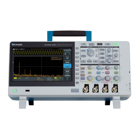
TBS2000B Series Oscilloscopes The TBS2000B offers the biggest display and longest record length in its class, so you can see more of your signals. It offers a powerful set of measurement and analysis tools with built-in tips make them easy to use. - Page 4 Required Equipment ◦ TBS2000B Series Oscilloscope Begin by exploring the controls and display of the TBS2000B Series. Then move on to a series of hands- ◦ Power Cord for your region (included with on exercises. Acquire waveforms, learn about triggering, take measurements, and learn how to save data.
-
Page 5: Setting Up The Equipment
Setting up the Equipment Power on the instrument 1. Plug in the power cord for your region 2. Press the power button to turn on the instrument. Allow the instrument’s power-up sequence to finish. 3. Connect probes to Channel 1 and Channel 2 To see the firmware version 1. -
Page 6: Front Panel T Our
Front Panel T our, Two-Channel Models HelpEverywhere and Scope Intro Multipurpose knob for 9-inch WVGA Display Waveform Navigation & One Touch Save Quick Oscilloscope Setup Power On/Off USB Flash Drive (Host) Probe Port Menu On/Off Compensation TekVPI™ Probe Output interface... - Page 7 Front Panel T our, Four-Channel Models Multipurpose knob for Waveform 9-inch WVGA Display Navigation & Quick Oscilloscope HelpEverywhere One Touch Save Setup and Scope Intro Probe Compensation Output Power On/Off Menu On/Off TekVPI™ Probe interface USB Flash Drive (Host) Port...
-
Page 8: Understanding The Display
Understanding the Display LAN Connectivity Wireless Indicator Waveform Connectivity Data Transfer Record View Trigger Status Indicator in process Acquisition Status HelpEverywhere Enabled Active Channel Channel Indicator Time/Date Hardware based Counter Vertical Scale Horizontal Scale Trigger Delay Sample Rate and Record Length... -
Page 9: Activating Helpeverywhere Tips
1. Activating HelpEverywhere Tips While you’re learning your way around the scope, HelpEverywhere provides helpful tips. Once you become proficient, you can turn the tips off if you wish. Press Help button on the front panel Press HelpEverywhere bezel button (Figure 1). Select Set All to On by pressing the Figure 1. -
Page 10: Using The Scope Intro Built-In Handbook
2. Using the Scope Intro Built- in Handbook If you get stuck, or want to know more about a particular control, Scope Intro provides a built-in, handy reference. Press Help button on the front panel Press Scope Intro bezel button (Figure 3) Select Oscilloscope Basic with the Multipurpose Knob (MPK) Figure 3. -
Page 11: Using Autoset To Acquire A Waveform
3. Using Autoset to Acquire a Waveform Autoset can often provide a stable signal display, automatically. Attach a TPP0100 passive probe to the Channel 1 BNC connector. Clip the probe tip to the Probe Comp output. Clip the ground clip to the Probe Comp ground terminal. -
Page 12: Triggering The Scope
4. Triggering the Scope (1/2) Although the square wave signal of the probe compensation does not require pulse width triggering, we will set it up for demonstration purposes. Keep Channel 1 connected to the Probe Comp output, as in demo 3. Press Default Setup in Resources section of the front panel Adjust the Vertical Scale on Channel 1 to 2.00V... - Page 13 4. Triggering the Scope (2/2) Although the square wave signal of the probe compensation does not require pulse width triggering, we will set it up for demonstration purposes. Note that the Source is CH1 and the Polarity is Positive Press Trigger When, and use the MPK to select Pulse Width >.
-
Page 14: Using Pan And Zoom To Navigate Through Long Records
5. Using Pan and Zoom to Navigate through Long Records (1/2) Especially for acquisitions of 20M points, it is important to be able to navigate through the record. Pan and zoom enable this. Press the Acquire button on the front panel. Notice that the Multipurpose Knob LED is on, which means it can be used to make a selection. - Page 15 5. Using Pan and Zoom to Navigate through Long Records (2/2) Especially for acquisitions of 5M points, it is important to be able to navigate through the record. Pan and zoom enable this. Set the zoom factor back to 100X. Press the Position bezel button.
-
Page 16: Using Cursors To Measure Time And Amplitude
6. Using Cursors to Measure Time and Amplitude(1/2) Cursors enable quick visual measurements on the selected waveform. The TBS2000B features on- waveform readouts to make it easy to visualize measurements. Press Default Setup. Press Autoset. Figure 10. Location of the Cursors and Fine Press the Cursors button beside the MPK buttons (two-channel model shown) (Figure 10). - Page 17 6. Using Cursors to Measure Time and Amplitude(2/2) Cursors enable quick visual measurements on the selected waveform. The TBS2000B features on- waveform readouts to make it easy to visualize measurements. Note the delta time readout between the cursors and the time position for each bar. Press MPK again to change control to the upper cursor for amplitude measurements.
-
Page 18: Making Automated Measurments
7. Making Automated Measurements (1/2) Automated measurements use the processing power of the scope to provide a frequency, time, amplitude, and area measurements. Connect passive probes to Channel 1 and Channel 2. Connect both probe tips to Probe Comp and both ground clips to Probe Comp ground. - Page 19 7. Making Automated Measurements (2/2) Automated measurements use the processing power of the scope to provide a frequency, time, amplitude, and area measurements. Press the CH1 bezel button. Scroll and press MPK to select Frequency and +Duty for Channel 1. Press the CH2 bezel button.
-
Page 20: Using An Fft To Analyze Signal's Frequency Spectrum
8. Using an FFT to Analyze a Signal’s Frequency Spectrum (1/2) The FFT function calculates the frequency input of the source waveform. Cursors make it easy to measure frequency and amplitude in the spectrum. Keep the TPP0100 passive probe connected to Channel 1 and the Probe Comp output. - Page 21 8. Using an FFT to Analyze a Signal’s Frequency Spectrum (2/2) The FFT function calculates the frequency input of the source waveform. Cursors make it easy to measure frequency and amplitude in the spectrum. The default FFT window is Hanning. Use the Window bezel button and MPK to switch to the Rectangular window and note the result.
-
Page 22: Saving Screen Images
9. Saving Screen Images (1/2) You can save screen images, waveform data, and setups to a USB flash drive. This demonstration shows how to save a screen image. Press Default Setup. Press Autoset. Plug a USB flash drive into the USB host port on the oscilloscope’s front panel. - Page 23 9. Saving Screen Images (1/2) You can save screen images, waveform data, and setups to a USB flash drive. This demonstration shows how to save a screen image. 10. Press the Save button outside the right top corner of the display(Figure 17) to save an image into the DEMO GUIDE folder on the USB thumb.
-
Page 24: Setting Up A Wireless Connection
10. Setting up a Wireless Connection The TBS2000B Series supports wireless communication through a USB to Wi-Fi adapter. To remotely control the scope, a PC, tablet or cell phone must be available and on the same network as the instrument. - Page 25 11. Remote Instrument Control (1/2) The built-in web server in the TBS2000B enables remote control from any device with an Ethernet connection and web browser. This demonstration requires a PC and an Ethernet cable. Note: If you established a wireless connection in the previous exercise, you can also use that connection.
- Page 26 11. Remote Instrument Control (2/2) The built-in web server in the TBS2000B enables remote control from any device with an Ethernet connection and web browser. This demonstration requires a PC and an Ethernet cable. Note: If you established a wireless connection in the previous exercise, you can also use that connection.
-
Page 27: Create And Load Custom Courseware
12. Create and load custom Bonus Addition equipment needed: courseware (1/3) • PC Courseware Editor Tool V2.0 Demo • USB drive The PC Courseware Editor helps you create lab descriptions and instructions on a PC and then upload the material directly onto a TBS2000B oscilloscope. You can modify existing labs with content that directly supports recent lectures or incorporates ideas discovered in class discussions. - Page 28 12. Create and load custom courseware (2/3) The PC Courseware Editor helps you create lab descriptions and instructions on a PC and then upload the material directly onto a TBS2000B oscilloscope. You can modify existing labs with content that directly supports recent lectures or incorporates ideas discovered in class discussions.
- Page 29 12. Create and load custom courseware (3/3) Follow the steps in Figure 27 to create a package that can be loaded on the TBS2000B Select the package and export it to a USB thumbdrive. Click Save and Quit once finished figure (Figure 26).
- Page 30 (Figure 30). Click Apply. Click Yes to confirm the setting. Figure 30. Tektronix and Keithley oscilloscopes, power supplies, digital multimeters and arbitrary function generators can all be added and managed from the TekSmartLab TSL300B software. See TekSmartLab user manual for setup instructions...
- Page 31 13. Configure a lab of instruments with TekSmartLab software (2/3) TekSmartLab is the industry's first network-based lab instrument management solution for quickly setting up and efficiently managing basic Instrumentation in engineering laboratories at colleges and universities. The centralized control of instruments enabled by the TekSmartLab solution dramatically improves the classroom and lab experience for students, instructors and lab managers.
- Page 32 13. Configure a lab of instruments with TekSmartLab software (3/3) TekSmartLab is the industry's first network-based lab instrument management solution for quickly setting up and efficiently managing basic Instrumentation in engineering laboratories at colleges and universities. The centralized control of instruments enabled by the TekSmartLab solution dramatically improves the classroom and lab experience for students, instructors and lab managers.
-
Page 33: Create Trend Plots Using Tekbench Software
Bonus • TekBench software • Demo USB cable TekBench™ is PC software that controls Tektronix • AFG31000 oscilloscopes and arbitrary function generators. It offers intuitive instrument control, automated measurement data logging, automated frequency response measurements and easy waveform exporting to eliminate extra time and effort. - Page 34 14. Create trend plots using TekBench software (2/2) TekBench™ is PC software that controls Tektronix oscilloscopes and arbitrary function generators. It offers intuitive instrument control, automated measurement data logging, automated frequency response measurements and easy waveform exporting to eliminate extra time and effort.
- Page 35 TEK.COM Copyright © Tektronix. All rights reserved. Tektronix products are covered by U.S. and foreign patents, issued and pending. Information in this publication supersedes that in all previously published material. Specification and price change privileges reserved. TEKTRONIX and TEK are registered trademarks of Tektronix, Inc. All other trade names referenced are the service marks, trademarks or registered trademarks of their respective companies.
Need help?
Do you have a question about the TBS2000B Series and is the answer not in the manual?
Questions and answers