Table of Contents
Advertisement
Available languages
Available languages
Quick Links
Advertisement
Table of Contents

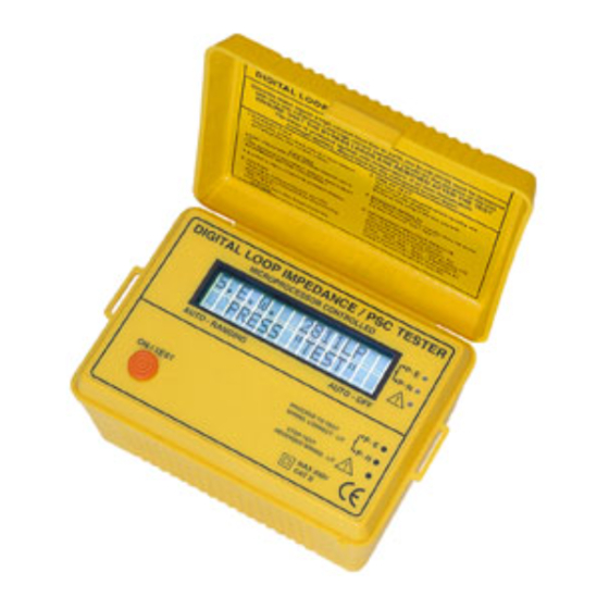
Summary of Contents for ADInstruments AD2811
- Page 1 AD INSTRUMENTS MEDIDOR DE IMPEDANCIA DE BUCLE AD2811. Manual de instrucciones...
-
Page 2: Table Of Contents
Índice Índice..............Precauciones de seguridad......... Especificaciones........... Notas de seguridad............3 Características............Conexiones............Diseño del equipo ……………………………………..Funciones.............. Preparación para la Medición......... Prueba de bucle / PSC / Tierra ......Batería..............Calibración y Mantenimiento ........ -
Page 3: Precauciones De Seguridad
...) No intente tomar ninguna medición o utilizar el probador. 1.6 El AD2811 ha sido diseñado para su seguridad. Sin embargo, no hay diseño puede proteger completamente contra usos incorrectos . Los circuitos eléctricos pueden ser peligrosos y / o letales. Tenga precaución en presencia de tensión por encima de 24V ya que estos representan un peligro de choque. -
Page 4: Conexiones
L-E y L-N Impedancia de lazo Cortocircuitos prospectivos L-E y L-N Espiga de Tierra , Linea e Impedancia del neutro 5. Conexiones 6. Diseño del equipo Prueba Scroll / Seleccione Menú Pantalla LCD. Leds indicadores del Cableado... -
Page 5: Funciones
● Tensión del Sistema El AD2811 esta diseñado para funcionar con 230 Vac. Sin embargo, si la tensión es menor, la prueba todavia se puede hacer pero la precisión podría deteriorarse debido al hecho de que la corriente inyectada es inferior a la óptima. Sin embargo, el equipo puede trabajar en una amplia gama de tensión y de cómputo para que esos cambios tengan un... -
Page 6: Prueba De Bucle / Psc / Tierra
Utilice conductores de mismo tamaño que el circuito RFT. ● Desenchufe todas las cargas A fin de no afectar a la medición, se han de desconectar toda la carga de la instalación bajo prueba. ● Hacer un esquema claro de la medición para poder interpretar resultados. ●... -
Page 7: Batería
10. Batería Reemplazo de la batería ● El equipo supervisa continuamente el voltaje de la batería y indica cuando la batería necesita ser reemplazado. ● Las baterías están situadas en el inferior del equipo. ● Desconecte los cables de prueba del instrumento, retire la tapa de las pilas y las baterías ●... - Page 8 AD INSTRUMENTS Hand Held Electrical Network Analyzer and Fault Finding Instrument. Instruction Manual DIGITAL “MULTIPLE” LOOP / PSC / EARTH TESTER...
- Page 9 Index Index………………………………………………….. Safety Precautions…………..……………………… Specifications………………………………………… Safety Notes…………………………………………. Features……………………………………………… Connections………………………………………….. Instrument Layout and System Connections……. Functions……………………………………………... Preparation for Measurement………………………. Loop / PSC / Earth testing ……………………….. Battery……………………………….……………….. Calibration & Servicing …………..…………………...
- Page 10 1. Safety Precautions Electricity can cause severe injuries, even with low voltages or currents. Therefore, it is extremely important that you read the following information before using your Digital Psc-Loop-Earth Tester and Electrical Network Analyzer. 1.1 This Instrument must only be used and operated by a competent trained person and in strict accordance with the instructions.
- Page 11 ● Measures: L-E and L-N voltages L-E and L-N Loop Impedance Prospective Short Circuits L-E and L-N Earth Spike, Line and Neutral Impedances 5. Connections 6. Instrument Layout and System Connections Test Scroll / Menu Select Large, High Contrast L.C.D. High Bright Wiring Check Led’s...
- Page 12 =Voltage of the generator (supply transformer) (internal impedance of transformer = X-Form) =Impedance of the Line wire from the transformer, up to the test point (Z displayed by Instrument also include X-Form). If this impedance is too high, check the connections of the Line wiring, check the quality of the line wiring and the switches / contacts in the line circuit.
- Page 13 ● Unplug all Load In order not to affect the measurement, it is avoided to unplug all load from the installation under test. ● Make a clear Sketch of measurement to be able to Interpret results. ● Check leads before using Tester. The Leads Quality and Resistance is a factor influence the accuracy of the results make sure they are always in good conditions.
- Page 14 10. Battery Battery Replacement ● The Tester continuously monitors the battery voltage and indicates when the battery need to be replaced. ● The tester’s batteries are situated under the test. ● Disconnect the test leads from the instrument, remove the battery cover and the batteries ●...


Need help?
Do you have a question about the AD2811 and is the answer not in the manual?
Questions and answers