Table of Contents
Advertisement
Quick Links
Technical Specifications
Power supply
∂ via the bus line
∂ KNX bus voltage: DC 24V (DC 21 ... 30 V) via KNX/EIB
bus line
∂ KNX bus current: 15 mA
Outputs
∂ 1 output (potential-free contact, bistable relay)
∂ switching characteristic:
set in parameter list according to application program
∂ rated voltage: 120, 277, 347 Vac, 50 / 60 Hz
Maximum load
20 A @ 347 Vac (General Purpose)
20 A @ 347 Vac Magnetic Ballast (200µF max.)
20 A @ 277 Vac (General Purpose)
20 A @ 277 Vac Ballast (200µF max.)
20 A @ 120 Vac (General Purpose)
20 A @ 120 Vac Ballast (200µF max.)
Control voltage
∂ 0/1 ... 10 V (provided by dimmable ballast)
∂ in case of bus voltage failure: 10 V
Control power
∂ dimmable electronic ballast according to IEC 60929
Annex E.2 or signal amplifier:
-
max 100mA @ 25°C (70°F)
e.g. 50 units 2mA each
-
max 85mA @ 45°C
-
Derating curve is linear.
∂ Protection against destruction by accidental connection
to mains voltage!
Control elements
∂ 1 learning button:
For switching between normal operating mode and
addressing mode
Display elements
∂ 1 red LED:
For monitoring bus voltage and for displaying normal
mode / addressing mode
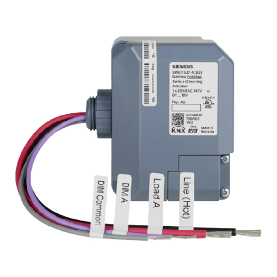
Product and Applications Description
The Switch-/Dimming Actuator is a KNX device for control-
ling up to one group (channels) of lamps via the
DC 0/1 -10 V control terminal of dimmable electronic ballasts
(ECGs). In addition there is a switching contact for direct
switching on/off of the connected lamps.
The device is installed into or attached to a 4 x 4 inch junc-
tion box. The bus is connected via a bus terminal block. The
actuator electronics are supplied via the bus voltage.
The channel of the Switch-/Dimming Actuator can control
several dimmable electronic ballasts. Their number is limited
by the switching capacity and by the control power. If the
on/off function is not used via the switching contact of the
Switch-/Dimming Actuator, the number of controllable ECGs
is only dependent on the load of the DC 1-10 V control volt-
age. This might allow controlling a larger number of ECGs
(see Technical Specifications below).
Various functions can be configured such as for switching
on/off lamps, dimming up / down or setting a particular
dimming level.
With the ETS (Engineering Tool Software) the application
program is selected, its parameters and addresses are as-
signed
appropriately
and
downloaded
Switch-/Dimming Actuator.
Amongst others, the application program includes an op-
tional counter for switching cycles and operating hours with
threshold monitoring for each output and an integrated 8-bit
scene control for incorporating the output into up to 8
scenes.
Each output of the actuator may be set to one of the follow-
ing operating modes:
- Normal operation
- Timer operation
Connections
∂ Bus line: Bus connection pins for connection of the
screwless bus terminal block (red-black) 0.6...0.8 mm Ø
single core, strip insulation 5mm
∂ Load circuit:
see Location and Function of Interface Elements
Physical specifications
∂ housing: plastic
∂ dimensions:
length : 70 mm (2.76 inch)
width: 90 mm (3.54 inch)
depth: 44.6 mm (1.76 inch)
∂ weight: approx. 195 g (7 oz)
∂ fire load: approx. 5 MJ
∂ Installation: in a junction box (min. dimensions)
Length: 4 inch (101.6 mm)
Width: 4 inch (101.6 mm)
Depth: 2-1/8 inch (54mm)
Electrical safety
∂ Degree of pollution (according to IEC 60664-1): 2
∂ Type of protection (according to IEC 60529): IP20
∂ Overvoltage category (according to IEC 60664-1): III
∂ Bus: safety extra low voltage SELV DC 24 V
∂ Relay with µ - contact
Environmental specifications
∂ Ambient operating temperature:
- 5 ... + 45 °C (+ 23 ... + 113 ↓F)
∂ Storage temperature:
- 25 ... + 70 °C (- 13 ... + 158 ↓F)
∂ Relative humidity (not condensing): 5 % ... 93 %
Reliability
∂ Failure rate: 411 fit at +40°C (+104°F)
instabus
instabus
USA
Switch-/Dimming Actuator
Switch
JB 5
527C23
5WG1 527-4CB23
5WG1 5
April 2017 / Page 1
April 2
Building site function
Building s
The building site function provided ex-factory enables
The building site function provided ex
switching the building site lighting on and off via bus wall
switching the building site lighting on and off via bus wall
switches and actuators, even if these devices have not yet
switches and actuators, even if these devices have not yet
been commissioned with ETS.
been commissioned with ETS.
Application Program
Application Program
The device needs
device needs the application program
"07 B0 A1
"07 B0 A1 Dimmer 983B01".
Example of Operation
Example of Operation
into
the
Listings and Certifications
Listings and Certifications
cULus listed (E464611)
listed (E464611)
UL 916, Open Energy Management Equipment
UL 916, Open Energy Management Equipment
CSA C22.2 No 205
CSA C22.2 No 205-12 Signal equipment
Markings
Markings
KNX, EIB, c
, cULus
Electromagnetic compatibility
Electromagnetic compatibility
complies with
complies with EN 61000-6-2 and EN 61000-6-3 (home
and industry levels)
and industry levels)
Canada: complies to
complies to CAN ICES-3(B)/NMB-3(B)
USA: complies with part 15 of the FCC Rules.
complies with part 15 of the FCC Rules.
Operation is subject to the following two conditions:
Operation is subject to the following two conditions:
(1) This device may not cause harmful interference,
(1) This device may not cause harmful interference,
and
(2) this device must accept any interference received,
device must accept any interference received,
including interference that may cause undesired opera-
including interference that may cause undesired oper
tion.
This equipment has been tested and found to comply
This equipment has been tested and found to comply
with the limits for a Class B digital device, pursuant to
with the limits for a Class B digital device, pursuant to
part 15 of the FCC Rules. These limits a
part 15 of the FCC Rules. These limits are designed to
provide reasonable protection against harmful interfe
provide reasonable protection against harmful interfer-
ence in a residential installation. This equipment gener-
ence in a residential installation. This equipment gene
ates, uses and can radiate radio frequency energy and,
ates, uses and can radiate radio frequency energy and,
if not installed and used in accordance with the instru
if not installed and used in accordance with the instruc-
tions, may cause har
tions, may cause harmful interference to radio commu-
nications. However, there is no guarantee that interfe
nications. However, there is no guarantee that interfer-
ence will not occur in a particular installation. If this
ence will not occur in a particular installation. If this
equipment does cause harmful interference to radio or
equipment does cause harmful interference to radio or
television reception, which can be determined by turn-
television reception, which can be determined by tur
ing the equipment off and on, the user is encouraged
the equipment off and on, the user is encouraged
to try to correct the interference by one or more of the
to try to correct the interference by one or more of the
following measures:
following measures:
•Reorient or relocate the receiving antenna.
•Reorient or relocate the receiving antenna.
•Increase the separation between the equipment and
•Increase the separation between the equipment and
receiver.
•Connect the equipment into an outlet on a circuit dif-
•Connect the equipment i
ferent from that to which the receiver is connected.
ferent from that to which the receiver is connected.
•Consult the dealer or an experienced radio/TV techni-
•Consult the dealer or an experienced radio/TV techn
cian for help.
cian for help.
Technical Manual
®
purple
red
black
P.T.O.
Advertisement
Table of Contents

Related Manuals for Siemens instabus JB 527C23


Summary of Contents for Siemens instabus JB 527C23
- Page 1 instabus instabus Technical Manual ® Switch Switch-/Dimming Actuator JB 5 527C23 5WG1 5 5WG1 527-4CB23 April 2 April 2017 / Page 1 Product and Applications Description Building s Building site function The Switch-/Dimming Actuator is a KNX device for control- The building site function provided ex The building site function provided ex-factory enables ling up to one group (channels) of lamps via the...
- Page 2 Can cause death, or serious injury or property damage. The device must not be opened. A faulty device should be returned to the local Siemens sales office or distributor. The device must be mounted and commissioned by a factory trained person.
Need help?
Do you have a question about the instabus JB 527C23 and is the answer not in the manual?
Questions and answers