Table of Contents
Advertisement
Quick Links
Technical Specifications
Power supply
• via the bus line
• KNX bus voltage:
DC 24V (DC 21...30V) via KNX/EIB bus line
• KNX bus current: < 10 mA
Outputs
• Mains connection:
carried out via the terminals for L and N of the actuator
• 1 drive channel with 2 relay contact outputs,
- rated voltage: AC 120 V, 50/60 Hz
• rated current: 6A (resistive load)
• switching current at DC 24 V:
-
6 A resistive load,
-
4 A inductive load (L/R = 7 ms)
Maximum load
6 A @ 120 Vac (General Purpose)
Control elements
1 learning button:
for switching between normal operating mode and
addressing mode
Display elements
1 red LED:
for monitoring bus voltage and for displaying normal
mode/addressing mode
Connections
• Bus line : Bus connection pins for connection of the
screwless bus terminal block (red-black) 0.6...0.8 mm
Ø single core, strip insulation 5mm
• Load circuit:
see Location and Function of Interface Elements
Product and Applications Description
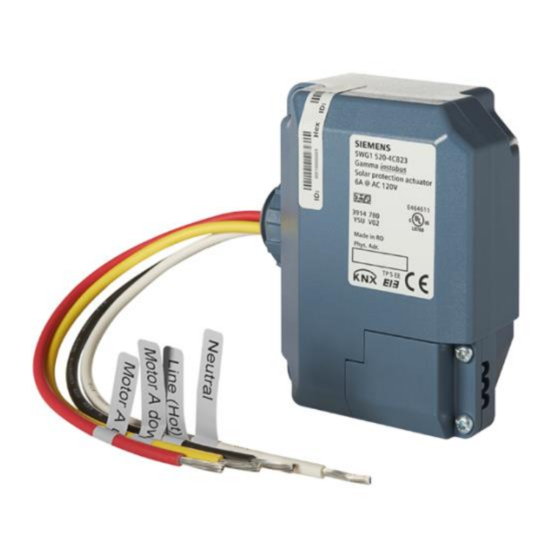
The JB520C23 solar protection actuator is a KNX device with
one relay output. The device is installed in a 4 x 4 inch junc-
tion box. The bus is connected via a bus terminal block. The
actuator electronics are supplied via the bus voltage.
The JB520C23 may be used to control blinds, shutters, awn-
ings, windows, or doors.
The device is designed to drive (per channel) one AC 120V
drive (motor) with electromechanical limit switches or with
integrated electronics for disconnection at the limit positions.
For drives with electromechanical limit switches the actuator
can be configured to detect the status of the electromechan-
ical limit switches such that the travel time between the end
positions can be measured via a synchronization run. The
travel time of the blind / shutter is automatically measured
from the upper end position to the lower end position and
vice versa. The measurement is only reliable for drives with
electromechanical limit switches. The travel time cannot be
automatically adjusted for drives with integrated electronics
for disconnection at the limit positions. These drives have to
be controlled via a time limit. Their travel times have to be
manually measured as precisely as possible and configured in
the application program.
Parallel operation of several drives on one channel requires
using a special separation relay. If such a separation relay is
connected to the output to drive several drives in parallel,
then the travel time has to be configured manually.
If the device is configured for automatic detection of the
travel time, then parallel operation of several drives with elec-
tromechanical limit switches or mixed operation with drives
with integrated electronics for disconnection at the limit po-
sitions is not permitted.
Physical specifications
• housing: plastic
• dimensions (L x W x D):
length : 70 mm (2.76 inch)
width : 90 mm (3.54 inch)
depth: 44.6 mm (1.76 inch)
• weight: approx 198 g
• fire load: approx. 5 MJ
• Installation: in a junction box (min. dimensions (L-W-D))
Length: 4 inch (101.6 mm)
Width: 4 inch (101.6 mm)
Depth: 2 inch (50.8 mm)
Electrical safety
• Degree of pollution (according to IEC 60664-1): 2
• Type of protection (according to EN 60529): IP 20
• Overvoltage category (according to IEC 60664-1): III
• Bus: safety extra low voltage SELV DC 24 V
• Device complies with: EN 50428
complies with EN 50428
Environmental specifications
• Ambient operating temperature:
- 5 ... + 45 °C (+ 23 ... + 113 F)
• Storage temperature:
- 25 ... + 70 °C (- 13 ... + 158 F)
• Relative humidity (not condensing): 5 % ... 93 %
Reliability
• Failure rate: 632 fit at 40°C
Markings
EIB, KNX, UL
instabus
USA
Solar protection actuator
JB520C23
5WG1520-4CB23
April 2020 / Page 1
Application Program
The JB520C23 Solar protection actuator (JB module) needs
the application program
"07 B0 A1 Shutter Actuator 982A01".
Example of Operation
Shutter / blind actuator JB520/23
K2
Up
K1
Down
Listings and Certifications
CE mark
complies with the EMC regulations (residential and func-
tional buildings) and low voltage regulations
UL listed (E464611)
UL 916, Open Energy Management Equipment
Technical Manual
®
Load circuit
AC
120
V
L1
N PE
Detection
4 N
of end
position
3 L
Venetian
blind motor
2
Up
M
Channel A
1~
1
Down
P.T.O.
Advertisement
Table of Contents

Related Manuals for Siemens instabus JB520C23


Summary of Contents for Siemens instabus JB520C23
- Page 1 instabus Technical Manual ® Solar protection actuator JB520C23 5WG1520-4CB23 April 2020 / Page 1 Product and Applications Description Application Program The JB520C23 solar protection actuator is a KNX device with The JB520C23 Solar protection actuator (JB module) needs one relay output. The device is installed in a 4 x 4 inch junc- the application program tion box.
- Page 2 Can cause death, or serious injury or property damage. The device must not be opened. A faulty device should be returned to the local Siemens sales office or distributor. The device must be mounted and commissioned by a factory trained person.
Need help?
Do you have a question about the instabus JB520C23 and is the answer not in the manual?
Questions and answers