Advertisement
Quick Links
s
Technical Specifications
Power supply
KNX bus voltage: via bus line
KNX bus voltage: DC 24 V
(DC 21 ... 30 V) via KNX bus line
KNX bus current: 15 mA
Outputs
1 outputs (potential-free contact, bistable relays)
switching characteristic:
set in parameter list according to application program
rated voltage: 120, 277, 347 Vac, 50 / 60 Hz
Maximum load
max. current per unit: 20A
20 A @ 347 Vac (General Purpose)
20 A @ 347 Vac Magnetic Ballast (200µF max.)
20 A @ 277 Vac (General Purpose)
20 A @ 277 Vac Ballast (200µF max.)
20 A @ 120 Vac (General Purpose)
20 A @ 120 Vac Ballast (200µF max.)
Control voltage
0/1 ... 10 V (provided by dimmable ballast)
in case of bus voltage failure: 10 V
Control power
dimmable electronic ballast according to
IEC 60929 Annex E.2 or signal amplifier:
- max 100mA @ 25°C (70°F) e.g. 50 units 2mA each
- max. 85mA @ 45°C
- Derating curve is linear.
Protection against destruction by accidental connection
to mains voltage!
Control elements
1 PROGRAMMING BUTTON: for switching between normal
operating mode and programming mode
Display elements
1 RED LED: for monitoring bus voltage and for displaying
normal mode/programming mode
Connections
KNX Bus: screwless "Push-Connect" standard KNX terminal
block (red/black). Connect can fit 4 pairs of terminations
BUS Wire: 18-22 AWG (0.6...0.8 mm) solid core, twisted,
shielded wire - strip insulation 5 mm.
Siemens wire: KNX-TSP20LC-CMP
Load circuit:
see Location and Function of Interface Elements
page 1 of 2
Product and Applications Description
The device is a KNX device for controlling one group (chan-
nels) of lamps via the DC 0/1 -10 V control terminal of dim-
mable LED drivers (ECGs). In addition, there is a switching
contact for direct switching on/off of the connected lamps.
The device is installed into or attached to a 4 x 4 inch junc-
tion box. The bus is connected via a bus terminal block. The
actuator electronics are supplied via the bus voltage.
The device can control several dimmable electronic bal-
lasts. Their number is limited by the switching capacity and
by the control power. If the on/off function is not used via
the switching contact, the number of controllable ECGs is
only dependent on the load of the DC 0/1-10 V control volt-
age. This might allow controlling a larger number of ECGs
(see Technical Specifications below).
Various functions can be configured such as for switching
on/off lamps, dimming up / down or setting a particular
dimming level.
Amongst others, the application program includes an op-
tional counter for switching cycles and operating hours
with threshold monitoring for each output and an inte-
grated 8-bit scene control for incorporating the output into
up to 8 scenes.
Physical specifications
housing: plastic
dimensions:
length: 70 mm (2.76 inch)
width: 90 mm (3.54 inch)
depth: 44.6 mm (1.76 inch)
weight: approx. 245 g (9 oz)
fire load: approx. 6 MJ
installation: in a junction box
minimal dimensions:
length: 4 inch (101.6 mm)
width: 4 inch (101.6 mm)
depth: 2-1/8 inch (54 mm)
Environmental specifications
Ambient operating temperature:
- 5 ... + 45 °C (+ 23 ... + 113 F)
Storage temperature:
- 25 ... + 70 °C (- 13 ... + 158 F)
Relative humidity (not condensing): 5 % ... 93 %
Reliability
Failure rate: 411 FIT at +40°C (104°F)
Electrical safety
Degree of pollution (according to IEC 60664-1): 2
Type of protection (according to IEC 60529): IP20
Overvoltage category (according to IEC 60664-1): III
Bus: safety extra low voltage SELV DC 24 V
Device complies with: IEC 63044-3
Markings
KNX, UL, cUL, PLENUM RATED
Listings and Certifications
UL listed (E464611)
UL 916 Enclosed Energy Management Equipment
UL 2043 Plenum Rated - Suitable for installation in Air
Handling or Plenum spaces
A6V11786013
Technical Manual
Switch/Dim Actuator
JB 527C23, 1 x AC 277 V
5WG1527-4CB23
PL
March 2022
LINK
Configuration
The device can be configured with Desigo Room Automa-
tion commissioning tool (ABT) or with KNX Engineering
Tool Software (ETS).
Example of Operation
Switch/Dim Actuator JB 527C23
DIM COMMON
Electromagnetic compatibility
USA:
This device complies with part 15 of the
FCC Rules. Operation is subject to the
following two conditions:
(1) This device may not cause harmful
interference, and
(2) this device must accept any interfer-
ence received, including interference
that may cause undesired operation.
This equipment has been tested and
found to comply with the limits for a
Class B digital device, pursuant to part
15 of the FCC Rules. These limits are de-
signed to provide reasonable protection
against harmful interference in a resi-
dential installation. This equipment gen-
erates, uses, and can radiate radio fre-
quency energy and, if not installed and
used in accordance with the instructions,
may cause harmful interference to radio
communications. However, there is no
guarantee that interference will not oc-
cur in a particular installation. If this
equipment does cause harmful interfer-
ence to radio or television reception,
which can be determined by turning the
equipment off and on, the user is en-
couraged to try to correct the interfer-
ence by one or more of the following
measures:
- Reorient or relocate the receiving an-
tenna.
- Increase the separation between the
equipment and
receiver.
- Connect the equipment into an outlet
on a circuit
different from that to which the receiver
is connected.
- Consult the dealer or an experienced
radio/TV
technician for help.
This device complies with Part 15 of the
FCC rules. Changes or modifications not
expressly approved by Siemens Schweiz
AG could void the user's authority to op-
erate the equipment.
United States representative:
https://new.siemens.com/us/en/prod-
ucts/buildingtechnologies/home.html
Canada:
CAN ICES-3(B)/NMB-3(B)
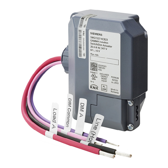
Load circuit
mains voltage
L
N
Electro nic driver
+
DIM A
purple
+ + + +
-
- - -
-
pink
N L
Load A
red
Line Hot
black
Advertisement

Subscribe to Our Youtube Channel
Related Manuals for Siemens JB 527C23


Summary of Contents for Siemens JB 527C23
- Page 1 Technical Manual Switch/Dim Actuator JB 527C23, 1 x AC 277 V 5WG1527-4CB23 March 2022 LINK Product and Applications Description Configuration The device is a KNX device for controlling one group (chan- nels) of lamps via the DC 0/1 -10 V control terminal of dim- The device can be configured with Desigo Room Automa- mable LED drivers (ECGs).
- Page 2 Can cause death, or serious injury or property damage. JB 527C23, 1 x AC 277 V The device must not be opened. A faulty device should be returned to the local Siemens sales office or distributor. 5WG1527-4CB23 The device must be mounted and commissioned by a factory trained person.
Need help?
Do you have a question about the JB 527C23 and is the answer not in the manual?
Questions and answers