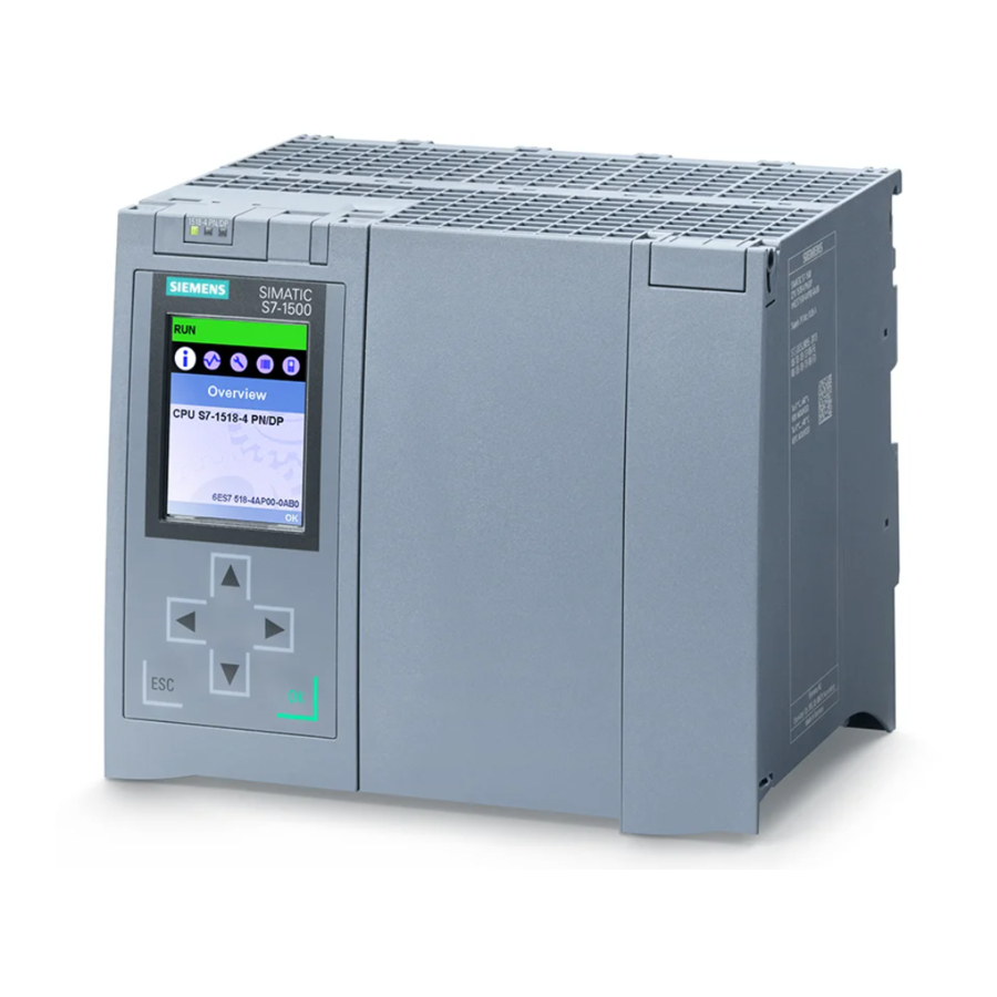
Siemens SIMATIC S7-1500 Manual
Hide thumbs Also See for SIMATIC S7-1500:
Table of Contents

Advertisement

The Technology
Objects (TO) of
SIMATIC S7-1500(T)
TIA Portal V14 / SIMATIC S7-1500 / SIMATIC S7-1500T
https://support.industry.siemens.com/cs/ww/en/view/109743134
Siemens
Industry
Online
Support

Advertisement

Table of Contents
loading

Summary of Contents for Siemens SIMATIC S7-1500

  • Page 1 The Technology Objects (TO) of SIMATIC S7-1500(T) Siemens TIA Portal V14 / SIMATIC S7-1500 / SIMATIC S7-1500T Industry Online https://support.industry.siemens.com/cs/ww/en/view/109743134 Support...
  • Page 2: Legal Information

    The foregoing provisions do not imply any change in the burden of proof to your detriment. You shall indemnify Siemens against existing or future claims of third parties in this connection except where Siemens is mandatorily liable.
  • Page 3: Table Of Contents

    Legal information ......................2 SIMATIC’s Technology Objects ............... 5 Motivation ..................... 5 Properties of a technology object (TO) ..........5 SIMATIC S7-1500 and SIMATIC S7-1500T......... 5 1.3.1 Technology objects for motion control ..........6 1.3.2 Technology objects for PID control ............7 1.3.3...
  • Page 4 Table of Contents 6.3.4 Application ..................27 "Cam Disc” Technology Object ..............28 General information ................28 Fields of application ................29 Application ..................29 Example Application ..................30 Configuration ..................30 8.1.1 Components used ................30 8.1.2 Functions .................... 31 8.1.3 Basis of realization ................
  • Page 5: Simatic's Technology Objects

    This guarantees a simple and standardized use of the motion control functionalities in the SIMATIC. SIMATIC S7-1500 and SIMATIC S7-1500T In the following chapters the technology objects available in the SIMATIC S7-1500 and in the SIMATIC S7-1500T are briefly introduced and explained. TOs of S7-1500(T) Entry ID: 109743134, V1.0,...
  • Page 6: Technology Objects For Motion Control

    1 SIMATIC’s Technology Objects 1.3 SIMATIC S7-1500 and SIMATIC S7-1500T 1.3.1 Technology objects for motion control Figure 1-1 Technology objects of the S7-1500 – motion control  Speed axis (TO_SpeedAxis) The "speed axis" (TO_SpeedAxis) technology objects presents the mechanical drive component in the controller. Jobs for specifying the speed of the drive can be placed using PLCopen motion control instructions.
  • Page 7: Technology Objects For Pid Control

    A cam disc technology object can be used multiple times in different technology objects. In comparison to SIMATIC S7-1500, the SIMATIC S7-1500T additionally supports the expanded synchronous functions. They offer the user the following further functions: ...
  • Page 8 1 SIMATIC’s Technology Objects 1.3 SIMATIC S7-1500 and SIMATIC S7-1500T  Universal control (PID_Compact) The PID_Compact technology object provides a universal PID control with integrated optimization. It corresponds to the instance data block of the PID_Compact instruction. When calling the PID_Compact instruction this data block also has to be transferred.
  • Page 9: Technology Objects For Counting And Measuring

    1 SIMATIC’s Technology Objects 1.3 SIMATIC S7-1500 and SIMATIC S7-1500T 1.3.3 Technology objects for counting and measuring Figure 1-3 Technology objects of the S7-1500 – counting and measuring  High-speed counter (High_Speed_Counter) The High_Speed_Counter technology object enables the easy configuration of counter modules for the operation with incremental and pulse encoders and their use in the user program.
  • Page 10: Hardware Configuration For "Motion Control

    2 Hardware Configuration for "Motion Control” 2.1 Basic configuration Hardware Configuration for "Motion Control” This chapter describes the basic hardware configuration of a motion control application with SIMATIC. In doing so, the general functions of the individual components are displayed. Basic configuration The basic hardware configuration of a motion control application is as follows: Figure 2-1 Basic hardware configuration...
  • Page 11: Control Loops Involved

    2 Hardware Configuration for "Motion Control” 2.2 Control loops involved Control loops involved When configuring a motion control application, whilst using the technology objects of the SIMATIC controller and the SINAMICS drive technology, the following control loops are involved in cascading configuration. Figure 2-2 Schematic diagram of the control loops involved Position Speed...
  • Page 12: Motion Control Resources

    2 Hardware Configuration for "Motion Control” 2.4 Motion control resources Figure 2-3 Isochronous data exchange For more information about setting up the isochronous data exchange between the individual components of your application, please refer to the links and literature in chapter 10, for example, in chapter "Adding and Configuring Drives in the Device Configuration"...
  • Page 13: "Axis" Technology Object

    3 "Axis” Technology Object 3.1 Speed axis (TO_SpeedAxis) "Axis” Technology Object Speed axis (TO_SpeedAxis) 3.1.1 General information The speed axis represents the simplest technology object to control an axis from SIMATIC. Figure 3-1 Speed axis (TO_SpeedAxis) The technology object takes on the easy and PLCopen-compliant transfer of the desired speed setpoint to the drive, in which the actual speed control of the axis or the motor takes place.
  • Page 14: Fields Of Application

    3 "Axis” Technology Object 3.2 Positioning axis (TO_PositioningAxis) 3.1.2 Fields of application The speed axis technology object can be used for applications for which no position feedback to user program is necessary. 3.1.3 Application This technology object can be used, for example, for the following applications: ...
  • Page 15: Fields Of Application

    3 "Axis” Technology Object 3.3 Synchronous axis (TO_SynchronousAxis)  "MC_MoveSuperimposed” Starting an additional superimposed movement to an already running basic movement.  "MC_TorqueLimiting” Enabling and configuring a force or torque limitation or a fixed stop detection for the position-controlled axis. This function can be enabled or disabled before or during a position-controlled movement.
  • Page 16 3 "Axis” Technology Object 3.3 Synchronous axis (TO_SynchronousAxis) The following conductance interconnections can be used in the process.  A linear relationship of the two axes to each other, for example, via a defined gear factor with relative or absolute position relationship between the slave and the master axis.
  • Page 17: Fields Of Application

    3 "Axis” Technology Object 3.3 Synchronous axis (TO_SynchronousAxis) axes is thus not necessary. However, it has to be made sure that setpoint jumps are avoided when the simulation is cancelled. At this point the slave and master axis should be standing above the position defined via the synchronous relationship.
  • Page 18: "External Encoder" Technology Object

    4 "External Encoder” Technology Object 4.1 General information "External Encoder” Technology Object General information The external encoder technology object present an incremental or absolute value encoder for position detection, which is equipped with a PROFINET interface and can therefore directly exchange data with the SIMATIC controller. Alternatively, a module of the ET 200SP or ET 200MP distributed I/O system for position detection, such as TM Count or TM PosInput could also be used here, which can communicate with the SIMATIC controller in accordance with the...
  • Page 19: Application

    4 "External Encoder” Technology Object 4.3 Application Application This technology object can be used, for example, for the following applications:  Detection of a running material line as master axis (conductance) of a processing module in a processing line for a modular machine configuration. ...
  • Page 20: "Measuring Input" Technology Object

    5 "Measuring Input” Technology Object 5.1 General information "Measuring Input” Technology Object General information The measuring input technology object is used for the highly precise detection of axis positions based on external switching signals. Figure 5-1 "Measuring input” technology object – selecting the detection The detection of the external switching signal can be performed in the following ways: ...
  • Page 21: Fields Of Application

    5 "Measuring Input” Technology Object 5.2 Fields of application  Measurement of both edges of the switching signal For this measurement function it can be additionally be configured with what edge of the switching signal the measurement is to be started. This is why this measurement function can be especially used for the length or distance measurement of passing through objects.
  • Page 22: Application

    5 "Measuring Input” Technology Object 5.3 Application Application This technology object can be used, for example, for the following applications:  Detecting the reference position of a modular processing station on a running material line as basis for the following processing steps. ...
  • Page 23: "Cam/Cam Track" Technology Object

    6 "Cam/Cam Track” Technology Object 6.1 General information "Cam/Cam Track” Technology Object General information The cam or cam track technology object is used for the highly precise output of switching signals, depending on the position of an axis or an encoder. For the output of switching signals it can be differentiated between the following two cam types: ...
  • Page 24: Time-Based Cams

    6 "Cam/Cam Track” Technology Object 6.1 General information 6.1.2 Time-based cams Contrary to distance output cams (position-based cams), time-based (output) cams are only defined by the absolute start position in relation to the axis. The cam length is the result of the also specified switch-on time of the cam. Here, it can also be generally differentiated between the setpoint and actual position of the axis.
  • Page 25: Activation Time

    6 "Cam/Cam Track” Technology Object 6.2 Cams (TO_OutputCam) Figure 6-5 Hysteresis 6.1.4 Activation time The activation time can define times for the two edges of a cam via which the switching delays of the actuator can be compensate for the signal output. This makes it possible to increase the precision of the cam output yet again in relation to the respective position of the axis or the encoder.
  • Page 26: Effective Direction Of Cams

    6 "Cam/Cam Track” Technology Object 6.3 Cam track (TO_CamTrack) 6.2.2 Effective direction of cams The effective direction of the cam can be specified via the direction input of the "MC_OutputCam” instruction. This means that the cam…  …is only switched in positive motion direction of the axis or the encoder and not when the axis moves in negative direction.
  • Page 27: Fields Of Application

    6 "Cam/Cam Track” Technology Object 6.3 Cam track (TO_CamTrack) Figure 6-7 Display of the cam track on the position of an axis 6.3.3 Fields of application The cam track technology object is used for applications where the several switching signals have to be precisely output on certain axis positions of an axis. The axis position of a virtual or real axis or also the position of an external encoder can be used as reference.
  • Page 28: "Cam Disc" Technology Object

    7 "Cam Disc” Technology Object 7.1 General information "Cam Disc” Technology Object General information The cam disc technology object defines the non-linear connection for a synchronous relationship between a slave and a master axis. The correlation of the position between the position of the master axis and the resulting position of the slave axis can be specified via the cam disc editor in graphical form.
  • Page 29: Fields Of Application

    7 "Cam Disc” Technology Object 7.2 Fields of application Fields of application A cam disc is always used when a slave axis is to move in absolute position-based synchronism to a master axis and there is no linear connection between the two axes.
  • Page 30: Example Application

    This documentation and the example project are valid for  TIA Portal or STEP 7 as of V14 update 2 and higher  SIMATIC S7-1500 as of firmware version V2.0 This application example has been created with the following hardware and software components: Hardware components...
  • Page 31: Functions

    8 Example Application 8.1 Configuration Component Qty. Article number Note Internet Explorer 11 Required for the display of the HTML user interface. V11.0.9600.16428 Example files and projects Table 8-3 Component Note 109743134_S7-1500T_TechnologyObjects This document. _DOC_v10_en.pdf 109743134_S7-1500T_TechnologyObjects Example project with virtual axes _PROJ_v10_en.zip for the use on a S7-1500T CPU without additional drives.
  • Page 32: Technology Objects Used

    8 Example Application 8.2 Technology objects used makes it possible to operate individual processing stations of the example application independent from each other. The processing stations of the sealing unit and for applying the material, then only monitor the data logger. If a new value is entered there by the measuring input, a new product was detected and the start positions for the two other processing stations can be calculated internally and the processing jobs can be started on the individual stations.
  • Page 33: Synchronous Axis (To_Synchronousaxis)

    8 Example Application 8.2 Technology objects used  Saving the conveyor belt position in which the product is located: The position of the conveyor belt detected via the measuring input technology object represents the belt position at which the product has reached the light barrier.
  • Page 34 8 Example Application 8.2 Technology objects used Note The shape of the cam disc is defined in the TIA Portal via the cam disc editor in the coordinate system of the cam disc. This coordinate system can be defined in the cam disc editor via the extension of the coordinate axis for the master axis (x) and the slave axis (f(x)).
  • Page 35: Cams (To_Outputcam)

    8 Example Application 8.3 Programming of the processing stations Segment Start Comment type f(x) f(x) Straight line Synchronism between product and sealing unit. A 1:1 synchronism between sealing unit and the product is achieved via the straight line with the slope 1 in the cam disc.
  • Page 36: Functional Principle Of The Example Application

    8 Example Application 8.3 Programming of the processing stations Figure 8-4 Joint data management in the "ProductPositionTable” data block Table 8-5 Configuration of the "ProductPositionTable” data block Data element Function Write index for the "PositionTable” array. WriteIndex_MeasuringInput If the position value was entered in the table through the measuring input unit, the index is increased by one or set to the next index (ring buffer function of "PositionTable”).
  • Page 37: Measuring Input

    8 Example Application 8.3 Programming of the processing stations The individual processing units therefore work totally independent from each other. The following principle applies:  If there is no difference between the read index of the unit and the write index the measuring input unit, there is no product for processing and the respective process remains in the dormant phase.
  • Page 38 8 Example Application 8.3 Programming of the processing stations //+++ Realize machine function +++ IF (#tempLatchProductPosition = True) THEN //Get actual write index #tempWriteIndex := #ProductPositionTable.WriteIndex_MeasuringInput; //Save actual position of product belt (product position) #ProductPositionTable.PositionTable[#tempWriteIndex] := #AxisProductBelt.ActualPosition; //Generate next write index (write pointer) //Incement index pointer #tempWriteIndex := #tempWriteIndex + 1;...
  • Page 39: Sealing Unit

    8 Example Application 8.3 Programming of the processing stations //+++ Call function block +++ #instMeasuringInput(MeasuringInput:=#MeasuringInput, Execute:=(#FunctionEnable AND NOT(#instMeasuringInput.Done)), Mode:=0); If a measured value was detected (instMeasuringInput.Done = True), virtually the same function as in the simulation will run. But now the measured value detected ("instMeasuringInput.MeasuredValue1”) is entered in the "PositionTable”...
  • Page 40 8 Example Application 8.3 Programming of the processing stations  Positioning axis technology object – master axis of the curve synchronization: Determination of the modulo settings of the technology object, in order to be able to correctly calculate the position for the start of the synchronism in relation to the position of the conveyor belt.
  • Page 41 8 Example Application 8.3 Programming of the processing stations //Calculate synchronizing parameter #statMasterOffset := #statSavedProductPosition + #PRODUCTBELT_SYNC_POSITION - #PRODUCTBELT_SYNC_DISTANCE; #statMasterStartDistance := #PRODUCTBELT_SYNC_DISTANCE; #statMasterSyncPosition := #PRODUCTBELT_SYNC_DISTANCE; //Check modulo settings IF (#tempModuloAxisMaster.Enable = True) THEN #tempModuloEndPosition := #tempModuloAxisMaster.StartValue + #tempModuloAxisMaster.Length; IF (#statMasterOffset > #tempModuloEndPosition) THEN #statMasterOffset := #statMasterOffset - #tempModuloAxisMaster.Length;...
  • Page 42 8 Example Application 8.3 Programming of the processing stations //Check modulo area of index pointer IF (#tempReadIndex > #ProductPositionTable.MaxIndex) THEN #tempReadIndex := #ProductPositionTable.MinIndex; END_IF; //Write back index pointer #ProductPositionTable.ReadIndex_SynchronousOperation := #tempReadIndex; //Set output signals #statBusy := False; #statError := False; #statErrorId := #ERRORID_DEFAULT;...
  • Page 43: Application Of Material

    8 Example Application 8.3 Programming of the processing stations  "MC_CamIn" The cam disc synchronization is started with a rising edge at the "execute” input. //+++ Realize machine function +++ //Function block calls //Interpolation (if cam disc is not interpolated) #instInterpolateCam(Cam := #CamDisc, Execute := NOT (#statCamIsInterpolated));...
  • Page 44 8 Example Application 8.3 Programming of the processing stations //+++ Get technology objects data +++ //Get modulo settings of master axis #tempModuloAxisMaster.Enable := #AxisMaster.Modulo.Enable; #tempModuloAxisMaster.StartValue := #AxisMaster.Modulo.StartValue; #tempModuloAxisMaster.Length := #AxisMaster.Modulo.Length; Checking the read and write index from the DB "ProductPositionTable” of the joint data management.
  • Page 45 8 Example Application 8.3 Programming of the processing stations //Check OffPosition IF (#statOffPosition > #tempModuloEndPosition) THEN #statOffPosition := #statOffPosition - #tempModuloAxisMaster.Length; END_IF; END_IF; //Start execution of function block #statEnable := True; Based on the falling edge on the "CamOutput” output of the "MC_OutputCam” technology function it is checked whether the output of the cam signal and thus the application of the material (end position of the cam reached) has been fully completed.
  • Page 46: Configuration Of The Tia Portal Project

    8 Example Application 8.4 Configuration of the TIA portal project //Save error id of the function block #statErrorId := #instMcOutputCam.ErrorId; //Stop execution of function block #statEnable := False; END_IF; Subsequently, the current status of the "CamOutput” output of the "MC_OutputCam” function is saved, in order to detect an edge from it in the next cycle.
  • Page 47: Program Blocks

    8 Example Application 8.4 Configuration of the TIA portal project 8.4.1 Program blocks The following program blocks are included in the TIA Portal project provided: The OB "Main” includes the calls of all blocks involved in the program. The OB "MC-Interpolator” and "MC- Servo"...
  • Page 48: Plc Data Types

    8 Example Application 8.4 Configuration of the TIA portal project 8.4.3 PLC data types The PLC data types are included in the TIA Portal project provided: The data types are divided in the same folder structure as the program blocks and include the appropriate PLC data types.
  • Page 49 8 Example Application 8.4 Configuration of the TIA portal project To be able to realize the cyclic data exchange as optimized as possible and without a high CPU load, all variables of the status data in the user program are transferred in two string tags (237 byte and 51 byte) packed and therefore only two variables are transferred to the HTML page.
  • Page 50: Operating The Application Example

    8 Example Application 8.5 Operating the application example Figure 8-7 JavaScript function on the HTML page to distribute the data Operating the application example 8.5.1 Downloading the project into the CPU Open the TIA Portal project of the example application, select the SIMATIC-CPU S7-1515T-2 PN in the project tree and load the entire project into the CPU via the context menu or the download icon.
  • Page 51: Calling The User Interface/Simulation

    8 Example Application 8.5 Operating the application example 8.5.2 Calling the user interface/simulation Connect your PC with the SIMATIC CPU and make sure that both devices are located in the same IP area (192.168.0.x). Then open the internet explorer and call the web server of the SIMATIC CPU there via the IP address 192.168.0.1.
  • Page 52 8 Example Application 8.5 Operating the application example Table 8-8 Operating options and display on the web page Operating option Start of the application example The conveyor belt (5) starts at the speed (4) selected. Stop of the application example The conveyor belt (5) is stopped.
  • Page 53 8 Example Application 8.5 Operating the application example Table 8-9 Operating options and display on the web page Display Speed of the conveyor belt Display of the current speed of the conveyor belt. Speed of the sealing unit Display of the current speed of the sealing unit The synchronism of the sealing unit to the product passing through can be monitored via the pointer position that displays the conveyor speed.
  • Page 54: "Sinamics V90 Pn" Demo Case

    9 "SINAMICS V90 PN” Demo Case 9.1 Overview of the demo case "SINAMICS V90 PN” Demo Case Overview of the demo case 9.1.1 Configuration of the case The "SINAMICS V90 PN” demo case consists of two SINAMICS V90 drives with the appropriate servo motors, one SIMATIC-CPU 1515T-2 PN and the ET 200SP distributed I/O system with the respective operating elements, such as, toggle switches, potentiometers and an emergency stop button.
  • Page 55: Wiring

    9 "SINAMICS V90 PN” Demo Case 9.1 Overview of the demo case  Emergency stop button for the delayed interruption of safety circuit of the two drives. The delay can be set via an "E-Stop Delay” potentiometer.  Potentiometer P1 and P2 to specify the voltage on the analog inputs of the AI 2xU module.
  • Page 56: Functions

    9 "SINAMICS V90 PN” Demo Case 9.1 Overview of the demo case Figure 9-2 Wiring of the "SINAMICS V90 PN” demo case CPU1515T ET200SP (192.168.0.1) (192.168.0.2) AI 2xU 00: P1 01: P2 TM Timer DI 00: Sensor 0° V90Left 01: Sensor 0° V90Right 02: S15 TM Timer DQ X1P1...
  • Page 57: Putting The Demo Case Into Operation

    9 "SINAMICS V90 PN” Demo Case 9.2 Putting the demo case into operation Putting the demo case into operation 9.2.1 Preparations  Installing TIA Portal V14  Installing HSP for SINAMICS V90 into the TIA Portal 9.2.2 Hardware configuration Set up the hardware configuration in the TIA Portal as follows: ...
  • Page 58: Operating The Application Example

    9 "SINAMICS V90 PN” Demo Case 9.3 Operating the application example 5. Apply the values in the drive 6. Permanently save the values in the drive (copy RAM to ROM) 7. Upload the values from the drive into the TIA Portal project. Operating the application example The operation of the example application corresponds to the approach introduced in chapter 8.5.
  • Page 59 9 "SINAMICS V90 PN” Demo Case 9.3 Operating the application example position of the positioning axis of the material line is transferred as product position to the data logger of the user program. The following code section from the "GetMeasuringInput” function block shows the real data logging via the "MC_MeasuringInput”...
  • Page 60: Links & Literature

    Topic Siemens Industry Online Support https://support.industry.siemens.com Download page of the entry https://support.industry.siemens.com/cs/ww/en/view/109743134 Isochronous mode with PROFINET - an example with SIMATIC S7-1500 https://support.industry.siemens.com/cs/ww/en/view/109480489 How Can You Integrate a Drive into the TIA Portal via the Device Master File (GSD)? https://support.industry.siemens.com/cs/ww/en/view/73257075...

This manual is also suitable for:

Simatic s7-1500tTia portal v14

Table of Contents