Table of Contents
Advertisement
Quick Links
Advertisement
Table of Contents

Related Manuals for Foamit DS4-2P Series


Summary of Contents for Foamit DS4-2P Series
- Page 1 Twin-Line Concentrate Doorway Foam Unit for 2-Part Products User Manual DS4-2P READ ALL INSTRUCTIONS BEFORE USING, OR SERVICING, THIS EQUIPMENT. KEEP THIS MANUAL IN A LOCATION THAT IS READILY AVAILABLE TO USERS AND SERVICE TECHNICIANS. English (Original Instructions)
-
Page 2: Table Of Contents
Contents Safety . . . . . . . . . . . . . . . . . . . . . . . . . . . . . . . . . . . . . . . . . . . . . . . . . . . . . . .3 System Overview . -
Page 3: Safety
Safety WARNING PEOPLE OR OBJECTS CAN BE HURT OR DAMAGED IF THIS UNIT IS NOT USED CORRECTLY! Failure to read all the instructions before operating the unit may result in personal injury or death from the improper use or the chemical solution. Anyone handling, operating or using the unit must read, and understand, the instructions in the manual. - Page 4 NOTICE Servicing, or modification, of this unit with parts not listed in this manual may cause the unit to operate improperly. Do not use unauthorized parts when servicing the unit. Use of an air lubricator before the unit may result in diminished performance and damage to the unit. Do not use an air lubricator before the unit.
-
Page 5: System Overview
System Overview System Overview The DS4-2P series of Twin-Line Concentrate Doorway Foam Units has multiple configurations. One control box can support up to three nozzle assemblies. Note: The combined distance between the control box and the nozzle(s) must equal 100 ft. (30.5 m) or less. The following tables provide information regarding model configuration, model hardware, system requirements and specifications. - Page 6 System requirements Compressed air requirements 40-80 psi (3-5 bar) with 5-10 cfm (141-283 l/min) 30-100 psi (2.1-6.9 bar) Water requirements Backflow prevention is required. Consult local plumbing ordinances for more information. Liquid temperature range 40-100˚F (4.4-37˚C) Electrical requirements 120 VAC at 60 Hz, 2 amps (GFCI protected outlet) Operating voltage 120 VAC Chemical products used with this equipment must be formulated for this type...
-
Page 7: Component Overview
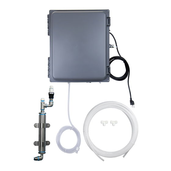
Component Overview Before you begin get to know the DS4-2P components that you will need to use, adjust or assemble. Control box 2. Timer 3 . Needle valve 4 . Power cord 5 . Water inlet 6 . Dual injector 7 . -
Page 8: Installation
Installation Preparation Remove all DS4-2P components from the packaging. 2 . Select an area to mount the control box. Note: The control box should be mounted to a vertical wall. We recommend mounting the control box at a height of 6 feet or less . The chemical suction line must reach the bottom of the chemical container. - Page 9 6 . Mount the stainless steel nozzle assembly in the desired location. Fasten the two stainless steel brackets using the screws and plastic anchors provided in the parts package. Repeat this step if multiple nozzles are Drills into wall needed. Connect the tubing from the solution outlet fitting on the control box to the solution inlet fitting on the nozzle assembly.
- Page 10 11 . Insert the proper metering tips and connect the chemical intake lines to the injector inlet barb. Timer Note: Use the metering tip color chart (below) to determine the appropriate metering tip based on the product and dilution rate. The model DS4-2P has two metering tips and two chemical intake lines.
-
Page 11: Operation
Operation Timer Setup The TR120DS-A is an adjustable repeat cycle timer with the ON time operating first. ON and OFF times can range from 1 second to 511 minutes. To set the timer: MIN/SEC SEC (off) / MIN (on) Starting with the OFF TIME, move the top dip switch to the left for MIN (minutes) or to the right for SEC OFF TIME (seconds) to select the desired time interval. -
Page 12: Maintenance
Maintenance WARNING Performing any maintenance with the unit turned ON, plugged into an electrical power source and connected to the air and water supply may serious injury or death. Always ensure that the unit has been turned OFF, unplugged from the electrical power source, and disconnected from the air/water supply before conducting any maintenance. -
Page 13: Troubleshooting
Troubleshooting Issue Solution Air Regulator Bowl or Air Filter has debris such as • Clean by unthreading the air regulator bowl from the air regulator. water, oil, or rust particles • The needle valve is open too far. Close and readjust the needle valve by Pump is cycling improperly opening the compressed air inlet valve. -
Page 14: Parts
Parts Control Box Assembly PB16138-A TR120DS-A P56-BRKT P56, P56K or P56V AG100 CV38-AP BVB14 HBSSEL1438 PN1238 ACV1 ACV1D38 WR1A SN1414 NV14Y HBELF3838 SSE12 SCI-125X2 WRG14 HBF3812 WR12SS QF1212 SSA12 Item number Description Item number Description 16 X 13 x 8 polypropylene control ACV1 MAC valve 1/4 in. -
Page 15: Nozzle Assembly
Nozzle Assembly QF1212 Item number Description 1/2 mpt x 1/2 fpt adjustable ball socket ABTN12 CV12F7-AP (polypropylene) 1/2 mpt threaded ball for ABTN12 QF1212 SN1212 ABTNTB12 (polypropylene) SSE12 SST12 1/2 Check valve 7 lb. spring - hastelloy CV12F7-AP spring - ep seals - acid proof - blk/wht SN1212 HHSB11412 1/2 in.
Need help?
Do you have a question about the DS4-2P Series and is the answer not in the manual?
Questions and answers