Advertisement
User's
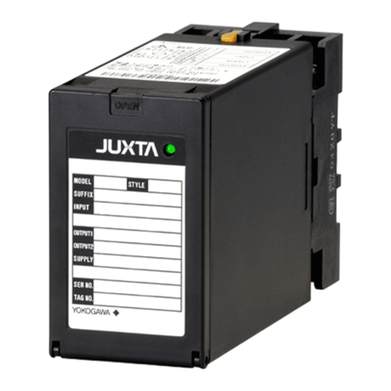
Model MU5
Manual
Universal Temperature
Converter
(Free Range Type)
IM 77J04U05-01E
Please read through this User's Manual before use for correct handling.
Please keep this User's Manual for future reference.
CAUTIONARY NOTES FOR SAFE USE
OF THE PRODUCT
This User's Manual should be carefully read before installing and oper-
ating the product. The following symbol is used on the product and in
this manual to ensure safe use.
This symbol is displayed on the product when it is neces-
sary to refer to the User's Manual for information on per-
sonnel and instrument safety. This symbol is displayed in
the User's Manual to indicate precautions for avoiding dan-
ger to the operator, such as an electric shock.
The following symbols are used only in this manual.
IMPORTANT
Indicates that operating the hardware or software in a particu-
lar manner may cause damage or result in a system failure.
NOTE
Draws attention to essential information for understanding
the operations and/or functions of the product.
CHECKING PRODUCT SPECIFICATIONS
AND PACKAGED ITEMS
(1) Checking the Model and Product Specifications
Check that the model and specifications indicated on the nameplate
attached to the main unit are as ordered.
(2) Packaged Items
Check that the package contains the following items:
G MU5: 1
G RJC sensor (A1167HT): 1
(RJC sensor is not attached for the optional specification
"/RJCN.")
G Spacer (for DIN rail mounting): 1
G Range label: 1
G User's Manual (this manual: IM 77J04U05-01E): 1
GENERAL
The MU5 is a plug-in type universal termperature converter that is con-
nected to an IEC/JIS-standard thermocouple, converts the tempera-
ture signals into isolated DC current or DC voltage signals.
IM 77J04U05-01E
Copyright© July 2005
3rd Edition Oct. 2007 (YK)
1
Network Solutions Business Division
2-9-32, Naka-cho Musashino-shi, Tokyo 180-8750 Japan
Phone: +81-422-52-7179
MODEL AND SUFFIX CODES
Model
Output
1: 1 output
Power supply
1: 15-40V DC (Operating range: 12 to 48 V)
6: 100-240 V AC/DC (Operating range: 85 to 264 V)
Input signal
U:Thermocouple, RTD, mV
Z: (Custom order)
Customized thermocouple or RTD
Output signal
A: 0 to 20 mA DC
Span is 5 mA or more
B: 0 to 5 mA DC
Span is 1 mA or more
1: −10 to +10 V DC
Span is 0.1 V or more
2: −100 to +100 mV DC
Span is 10 mV or more
Z: (Custom order)
Customized current signals or voltage signals
Optional specification
/SN: Without socket
/RJCN: Without RJC sensor
Facsimile: +81-422-52-6619
MU5 -01 -
00 /
Advertisement
Table of Contents

Related Manuals for YOKOGAWA JUXTA MU5-01 00 Series


Summary of Contents for YOKOGAWA JUXTA MU5-01 00 Series
- Page 1 User’s Model MU5 Manual Universal Temperature Converter (Free Range Type) IM 77J04U05-01E Network Solutions Business Division 2-9-32, Naka-cho Musashino-shi, Tokyo 180-8750 Japan Phone: +81-422-52-7179 Facsimile: +81-422-52-6619 Please read through this User’s Manual before use for correct handling. Please keep this User’s Manual for future reference. IM 77J04U05-01E Copyright©...
-
Page 2: Mounting Method
MOUNTING METHOD 3. EXTERNAL WIRING NOTE WARNING Plug/disconnect the main unit into/from the socket To avoid the risk of an electric shock, turn off the power vertically to the socket face. Otherwise the terminals may supply and use a tester or similar device to ensure that no bend and it may cause bad contact. -
Page 3: Description Of Front Panel
Power Supply and Isolaion 4.3 Selection Switch and Adjustment Switch Power supply rated voltage: The following adjustments can be performed using the switches on the 15-40 V DC or 100-240 V AC/DC 50/60 Hz front panel (selection switch and adjustment switch) without the dedi- Power supply input voltage: cated setting tool (refer to“4.2 Connector for Communication”). -
Page 4: Setting Parameters
Setting Input Range 4.3.3 Turning on/off the RJC Using the Switches on the Set the input range 0% in [D27:INPUT1L_RNG], and the input range Front Panel. 100% in [D28:INPUT1H_RNG]. This operation is only for thermocouple input. Turn the selection switch to “7”. Turn the adjustment switch coun- Correcting Wiring Resistance terclockwise to turn off the RJC sensor after 1 second. -
Page 5: Maintenance
Calibration Apparatus G A DC voltage/current standard (Yokogawa 7651 or the equivalent) G A 6-dial variable resistor (Yokogawa M&C 27931 or the equivalent) G A digital mutimeter (Yokogawa 7561 or the equivalent) G A precision resistor of 250 Ω ±0.01%, 1 W G A setting tool for adjustment (Refer to “4.2 Connector for Communication”... - Page 6 IM 77J04U05-01E 3rd Edition Oct. 15, 2007-00...
Need help?
Do you have a question about the JUXTA MU5-01 00 Series and is the answer not in the manual?
Questions and answers