Table of Contents
Advertisement
Quick Links
User's
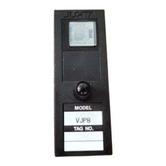
Model VJP8
Pulse Rate Converter
Manual
(Multi-function)
(Isolated Single-output and Isolated Dual-
output Types)
Thank you for purchasing the JUXTA Signal Conditioner.
Please read through this manual before use for correct handling.
CAUTIONARY NOTES FOR SAFE USE OF THE
PRODUCT
This User's Manual should be carefully read before installing
and operating the product. Please keep this User's Manual for
future reference.For more information of the safety precautions,
please refer to the "Precautions on the Use of the JUXTA
Series (IM 77J01A00-91Z1)". The related manuals and general
specifications are shown in the table below.
Doc. Name
Precautions on the Use of the JUXTA Series (User's
Manual)
Model VJP8 Pulse Rate Converter (User's Manual)
Model VJP8 Pulse Rate Converter (General Specifications) GS 77J01P08-01E
User's manuals in the above table are essential parts of the
product; keep it in a safe place for future reference.
This manual is intended for the following personnel;
•
Engineers responsible for installation, wiring, and maintenance
of the equipment.
•
Personnel responsible for normal daily operation of the
equipment.
The following symbol is used on the product and in this manual to
ensure safe usage.
WARNING
Calls attention to actions or conditions that could
cause serious or fatal injury to the user, and indicates
precautions that should be taken to prevent such
occurrences.
CAUTION
Calls attention to actions or conditions that could
cause injury to the user or damage to the instrument
or property and indicates precautions that should be
taken to prevent such occurrences.
QR Code
The product has a QR Code pasted for efficient plant
maintenance work and asset information management.
It enables confirming the specifications of purchased products
and user's manuals.
For more details, please refer to the following URL.
https://www.yokogawa.com/qr-code
* QR Code is a registered trademark of DENSO WAVE
INCORPORATED.
CHECKING PRODUCT SPECIFICATIONS
AND PACKAGE
(1) Checking the Model and Product Specifications
Check that the model and specifications indicated on the
nameplate attached to the main unit are as ordered.
(2) Packaged Items
Check that the package contains the following items:
•
VJP8: 1 unit
IM 77J01P08-01E
6th Edition July 2023 (YK)
Doc. Number
IM 77J01A00-91Z1
IM 77J01P08-01E
(This manual)
1
2-9-32, Naka-cho Musashino-shi, Tokyo 180-8750 Japan
Phone: +81-422-52-7179
Facsimile: +81-422-52-6793
You can download the latest manuals from the following website:
http://www.yokogawa.com/ns/juxta/im/
Standard Accessories:
•
Tag number label: 1 sheet
•
Range label: 1 sheet
•
Socket (T9093FL): 1 piece
(when /SN option is not specified.)
•
Shunt resistor(E9786WL):1 piece
(When optional code /R is specified)
•
User's Manual (
IM 77J01P08-01E,
•
User's manual (IM 77J01A00-91Z1): 1 copy
GENERAL
•
This compact plug-in type pulse rate converter receives pulse
signals from the field and converts them into various isolated
pulse outputs at a set pulse rate. It can also operate as a
pulse repeater (input frequency = output frequency) by setting
the pulse rate and pulse width type.
MODEL AND SUFFIX CODES
Model
Suffix codes
VJP8
-0
x
x
-x
x
x
-0
1
Output
2
6
Power supply
7
-1
Transmitter power
supply
-2
1
3
Output-1 signal
5
6
7
1
3
5
Output-2 signal
6
7
P
N
Options
*1 Operating range: 85 to 264 V AC/DC
*2 Operating range: 12 to 36 V DC
*3 When specifying contactless AC switch and suffix codes /C0 or /FB,
CE marking is not applicable because the product does not conform to
safety and EMC standards.
Note: An exclusive User's Manual might be attached to the
products whose suffix codes or option codes contain the code
"Z" (made to customers' specifications). Please read it along
with this manual.
this manual): 1 copy
Description
Pulse Rate Converter
0
/x
(Multi-function)
Always -0
1 output
2 outputs
100-240 V AC/DC
(*1)
15-30 V DC
(*2)
12 V DC ±10%
24 V DC ±10%
Open collector (30 V DC/200 mA)
Contactless AC switch
(*3)
Voltage pulse (5 V ±10%)
Voltage pulse (12 V ±10%)
Voltage pulse (24 V ±10%)
Open collector (30 V DC/200 mA)
Contactless AC switch
(*3)
Voltage pulse (5 V ±10%)
Voltage pulse (12 V ±10%)
Voltage pulse (24 V ±10%)
Communication function (RS-485)
No output-2
0
Always 0
No socket (with socket if not
/SN
specified)
With 200 Ω shunt resistor
/R
(Specify when current pulse input.)
/C0
Coating
(*3)
/FB
Fuse bypass
(*3)
Advertisement
Table of Contents

Subscribe to Our Youtube Channel
Related Manuals for YOKOGAWA JUXTA VJP8


Summary of Contents for YOKOGAWA JUXTA VJP8
- Page 1 Types) Phone: +81-422-52-7179 Facsimile: +81-422-52-6793 You can download the latest manuals from the following website: http://www.yokogawa.com/ns/juxta/im/ Thank you for purchasing the JUXTA Signal Conditioner. Please read through this manual before use for correct handling. IM 77J01P08-01E 6th Edition July 2023 (YK)
- Page 2 MOUNTING METHOD INSTALLATION AND ENVIRONMENTAL CONDITIONS CAUTION • Avoid the following environments for installation locations: ● Plug/disconnect the main unit into/from the Areas with vibrations, corrosive gases, dust, water, oil, socket vertically to the socket face. Otherwise the solvents, direct sunlight, radiation, a strong electric field, terminals may bend and it may cause bad contact.
- Page 3 EXTERNAL WIRING Pulse output connection example WARNING Voltage pulse Open collector ● To avoid the risk of an electric shock, turn off the 5 V, 12 V, 24 V power supply and use a tester or similar device to Load Load ensure that no power is supplied to a cable to be connected, before carrying out wiring work.
- Page 4 5.1.6 Input Filter DESCRIPTION OF FRONT PANEL When the chattering noise is generated in input, the input filter 4.1 Front Panel is used to restrain the influence. Select and set "ON" in [D58: INPUT FILTER], then the input The communications connector in the front panel is used for filter for time constant of about 10ms will be connected.
- Page 5 TAG NO Tag no. SELF CHK Self-check result 7.1 Calibration Apparatus DISPLAY1 Display1 • A calibrator (YOKOGAWA CA500 or equivalent) INPUT1 Input value 1 COUNTER1 Integrating counter 1 (*3) 7.2 Calibration Procedure COUNTER2 Integrating counter 2...
- Page 6 Measurement Description Remarks category (other) For measurements performed on circuits not directly connected to MAINS. CAT.II For measurements Appliances, performed on circuits directly portable connected to the low-voltage equipments, installation. etc. CAT.III For measurements Distribution performed in the building board, circuit installation.
Need help?
Do you have a question about the JUXTA VJP8 and is the answer not in the manual?
Questions and answers