Table of Contents
Advertisement
Advertisement
Table of Contents

Related Manuals for Numatics G3 Series


Summary of Contents for Numatics G3 Series
- Page 1 G3 Series EtherNet/IP Technical Manual...
- Page 2 (2) The PRODUCT has been designed and manufactured for use in general industries. Numatics Incorporated shall have no responsibility or liability including but not limited to any and all responsibility or liability based on contract, warranty, tort, product liability for any injury or death to persons, loss or damage to property caused by the product that are operated or used in application not intended or excluded by instructions, precautions or warnings contained in Numatics Inc.
- Page 3 All Numatics Inc. communication nodes should be grounded during the installation process. These grounding guidelines can be found in National Electrical code IEC 60204-1 or EN 60204-1. • All Numatics G3 Electronics Products to be installed or wired in accordance with ASCO Numatics published instructions and applicable electrical codes. •...
-
Page 4: Table Of Contents
G3 Series EtherNet/IP DLR Technical Manual Table of Contents 1. About EtherNet/IP ..............................6 Overview ................................6 G3 EtherNet/IP Features..........................6 G3 EtherNet/IP Performance Data ........................6 2. G3 Introduction ............................... 7 G3 Electronics Modularity............................. 8 500 Series Pneumatic Valve Manifold........................9 500 Series Manifold Stations ..........................10... - Page 5 14. EtherNet/IP Commissioning ..........................139 14.1 G3 configuration for RSLogix 5000 (Rockwell Generic Ethernet Module) ............139 14.2 G3 configuration for RSLogix 5000 (Numatics G3 EDS File) ................141 15. EtherNet/IP Mapping ............................144 15.1 I/O Sizes ................................144 15.2 Manifold and I/O Data Sizing Worksheet ......................
-
Page 6: About Ethernet/Ip
G3 Series EtherNet/IP DLR Technical Manual 1. About EtherNet/IP Overview EtherNet/IP is a communication protocol that uses the same network technology that can be found in commercial and domestic operations worldwide, but has added benefits/features toward manufacturing applications. It is a CIP (common industrial protocol) Network that follows the Open Systems Interconnection (OSI) model. -
Page 7: G3 Introduction
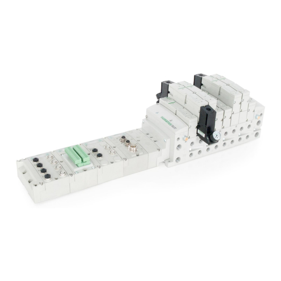
DLR Technical Manual 2. G3 Introduction The G3 Series is an electronic product platform that features an integrated graphic display for simple commissioning and displaying of diagnostic information. The G3 offers innovative distribution capability which allows the same I/O components that make up a centralized manifold configuration to be used as the distribution components as well, decreasing the need for duplicate components on centralized and distributed applications. -
Page 8: G3 Electronics Modularity
DLR Technical Manual G3 Electronics Modularity Discrete I/O The G3 Series product line is a completely modular and scalable system. As shown below, the G3 electronic modules plug together, via mechanical clips, allowing for easy assembly and field changes. TDG3EDM1-6EN... -
Page 9: Series Pneumatic Valve Manifold
G3 Series EtherNet/IP DLR Technical Manual 500 Series Pneumatic Valve Manifold The pneumatic valve manifold with internal circuit board technology is also modular. The valve solenoid coil connections are automatically made using Z-Board technology (plug together PC boards), which allow internal connection from solenoid coils ™... -
Page 10: Series Manifold Stations
G3 Series EtherNet/IP DLR Technical Manual 500 Series Manifold Stations Solenoid Coil Connections using Z-Board™ Technology for 50x valve series Z-Board ™ plug together technology connects all valve solenoids to the valve coil output driver board, located in the valve adapter. -
Page 11: Series Standard Z-Board™ Connectors
G3 Series EtherNet/IP DLR Technical Manual 500 Series Standard Z-Board™ Connectors The 501, 502 and 503 valve series utilize 2 different Z-Board ™ designs to achieve the single and double solenoid output functions. 502 Series 501 Series 503 Series TDG3EDM1-6EN... -
Page 12: 2000 Series Pneumatic Valve Manifold
G3 Series EtherNet/IP DLR Technical Manual 2000 Series Pneumatic Valve Manifold The pneumatic valve manifold with internal circuit board technology is also modular. The valve solenoid coil connections are automatically made using Z-Board technology (plug together PC boards), which allow internal ™... -
Page 13: 2000 Series Z-Board™ Connectors
G3 Series EtherNet/IP DLR Technical Manual 2000 Series Z-Board™ Connectors The 2005/2012/2035 valve series utilize 2 different Z-Board ™ designs to achieve the single and double solenoid output functions. This yields the possible 32 single, 16 double, or various combinations of valve coil output capabilities. -
Page 14: 2000 Series Z-Board™ And Ribbon Cable Example
G3 Series EtherNet/IP DLR Technical Manual 2000 Series Z-Board™ and Ribbon Cable Example If fourteen (14) single solenoid and one (1) double solenoid valves are connected directly to the communication node through the associated Z-Boards ™ . one (1) single solenoid and four (4) double solenoid valves are connected... -
Page 15: 2000 Series Z-Board™ With Valve Side Sub-D Example
G3 Series EtherNet/IP DLR Technical Manual 2000 Series Z-Board™ with Valve Side Sub-D Example If sixteen (16) single solenoid valves are connected directly to the communication node via Z-Boards ™ and a valve side Sub-D connector is connected to the communication node via the output Group No. 2 connector then the... -
Page 16: Zoned Power
G3 Series EtherNet/IP DLR Technical Manual 3. Zoned Power 503 Series Zoned Power application The Zoned Power Manifold blocks can be incorporated into a 503 manifold assembly to isolate Power to a number of valve stations, independent from the main power of the manifold. This is achieved by the integral 4 Pin M12 connector along with the modified manifold board. -
Page 17: Series Zoned Power Example
G3 Series EtherNet/IP DLR Technical Manual 503 Series Zoned Power example In the example shown below there are two Zoned Power Manifold blocks used. One is a "W" wiring option and the other is a "V" wiring option. The first (5) stations of the manifold assembly get their power from the M12 4 Pin connector at station one. -
Page 18: Communication Module
G3 Series EtherNet/IP DLR Technical Manual 4. Communication Module EtherNet/IP DLR Communication Module (Node) This module is the communication interface to the manifold. It contains communication electronics and internal short circuit protection for power. It can be configured using the module’s internal webserver or graphic display interface. -
Page 19: Communication Module Description
G3 Series EtherNet/IP DLR Technical Manual Communication Module Description Detail No. Description “Set” Button – used to navigate through user menus and to set parameters Activity/Link Status LED Two - 4 Pin M12 D-Coded Female Communication Connectors Mounting Hole “Next” Button – used to navigate through user menus and to set parameters Graphic Display –... -
Page 20: Connector Pin-Outs
G3 Series EtherNet/IP DLR Technical Manual Connector Pin-Outs Industry standard connectors are used for communication and auxiliary power. The EtherNet/IP communication connector is a D-coded keyway 4 pin female M12 connector. The Power connector is a single keyway 4 pin male 7/8” MINI connector. -
Page 21: Electrical Connections
G3 Series EtherNet/IP DLR Technical Manual Electrical Connections Power Connector Wiring Diagram Power Supply Example (Non-isolated commons) Power Supply Example (Isolated commons) • Please see page 25 for external fuse sizing guide. • When using molded connector power cables, Do Not rely on wire colors for Pin- Out. - Page 22 RX+ (WHITE/GREEN) RX+ (WHITE/GREEN) G3 Series EtherNet/IP DLR Technical Manual STRAIGHT-THROUGH MALE MALE CABLE EtherNet/IP Cabling Diagram TX- (ORANGE) TX- (ORANGE) Here are some basic wiring examples of Straight-Through cabling. Crossover cabling is not required for the G3 Ethernet IP DLR module.
-
Page 23: Ground Wiring
G3 Series EtherNet/IP DLR Technical Manual Ground Wiring All Numatics Inc. communication nodes should be grounded during the installation process. These grounding guidelines can be found in National Electrical code IEC 60204-1 or EN 60204-1. CHASSIS GROUND CONNECTION POINTS •... -
Page 24: Power Consumption
G3 Series EtherNet/IP DLR Technical Manual Power Consumption Power Connection ENELEC Function Description Pin No. +24 VDC Voltage used to power outputs (Valves and Outputs) (valve coils and discrete outputs) SW +24 VDC Voltage used to power discrete inputs and... - Page 25 G3 Series EtherNet/IP DLR Technical Manual Recommended External Fuses External fuses should be chosen based upon the physical manifold configuration. Please refer to the following table for the fuse sizing chart. External Fuse Sizing Chart Power Consumption - Power Connector Pin for Valves and Outputs...
-
Page 26: Diagnostics
G3 Series EtherNet/IP DLR Technical Manual Diagnostics Communication Module LED Functions Upon power up, the LEDs indicate the status of the unit. There are five LEDs on the G3 EtherNet/IP node. The LEDs are described below. LED Name Color Status... - Page 27 G3 Series EtherNet/IP DLR Technical Manual G3 Output modules incorporate short circuit protection and diagnostics to identify short circuit, open coils and over temperature conditions. The diagnostics can be accessed within the user PLC program or the G3 Ethernet/IP node’s integrated webpage.
-
Page 28: G3 Graphic Display
G3 Series EtherNet/IP DLR Technical Manual 5. G3 Graphic Display The G3 Communication and I/O modules feature an integrated graphic display used to configure parameters and display diagnostic information. The graphic displays on the following page represent the main menu selections of the EtherNet/IP communication module (node). -
Page 29: Main Menu Structure
G3 Series EtherNet/IP DLR Technical Manual Main Menu Structure Use the NEXT button to scroll through the Main menu headings shown below. At this level pressing the SET button allows access the Sub-Menus. Please see the appropriate page referenced below for further details and descriptions of the Sub- Menus. -
Page 30: Ip Address
G3 Series EtherNet/IP DLR Technical Manual IP Address Steps to Set IP Address IP ADDRESS Press the SET button to enter the IP ADDRESS sub-menu. 192.168.3.120 Press the NEXT button to select the octet that you would like to IP ADDRESS 192.168.3.120... -
Page 31: Subnet Mask
G3 Series EtherNet/IP DLR Technical Manual Subnet Mask Steps to Set Subnet Mask Press the SET button to enter the Subnet Mask sub-menu. SUBNET MASK 255.255.255.0 Press the NEXT button to select the octet that you would like to change. -
Page 32: Gateway Ip
G3 Series EtherNet/IP DLR Technical Manual Gateway IP Steps to Set Gateway IP Press the SET button to enter the Gateway IP sub-menu. GATEWAY IP 0.0.0.0 Press the NEXT button to select the octet that you would like to change. -
Page 33: Dhcp-Bootp
G3 Series EtherNet/IP DLR Technical Manual DHCP-BOOTP This will allow the enabling / disabling of the DHCP (Dynamic Host Control Protocol) and / BOOTP parameters. Enabling this parameter will allow the IP Address to be set via a BOOTP/DHCP server. -
Page 34: Config. Mode
G3 Series EtherNet/IP DLR Technical Manual Config. Mode Config Mode Settings Press the SET button to enter the Config Mode sub-menu. CONFIG MODE Press the SET button to change this parameter to 32, 64, CONFIG MODE 96 or 128 Press the NEXT button to select Yes or No. -
Page 35: Web-Server
G3 Series EtherNet/IP DLR Technical Manual Web-Server This will allow the enabling/disabling of the G3 Web Server. Web-Server Steps Press the SET button to enter the Web-Server sub-menu. WEB-SERVER ENABLED Press the NEXT button to scroll through the choices to WEB-SERVER enable or disable the feature. -
Page 36: Mac Address
G3 Series EtherNet/IP DLR Technical Manual MAC Address MAC (Machine Access Control) Address The MAC Address is a fixed unique value that cannot be MAC ADDR edited. 0.15.24.00.00.06 The actual MAC ADDR has an extra leading zero. The actual number in the example shown is 00-15-24-00-06-69 NOTE! •... -
Page 37: Advanced Settings - Comm. Fault
G3 Series EtherNet/IP DLR Technical Manual Advanced Settings – Comm. Fault This will allow the enabling / disabling of the Fault Action parameter. The Fault Action parameter determines the behavior of the outputs during a communication fault. Please see page 138 for more details. -
Page 38: Advanced Settings - Brightness
G3 Series EtherNet/IP DLR Technical Manual 5.10 Advanced Settings - Brightness Brightness Settings Press the SET button to enter the ADVANCED SETTINGS menu. ADVANCED SETTINGS Press the NEXT button to scroll to the CONFIG MENU / SET ADVANCED ADVANCED BRIGHTNESS. -
Page 39: Advanced Settings - Flip Display
G3 Series EtherNet/IP DLR Technical Manual 5.11 Advanced Settings – Flip Display Flip Display Settings Press the SET button to enter the ADVANCED SETTINGS ADVANCED SETTINGS menu. ADVANCED MENU ADVANCED MENU FLIP DISPLAY FLIP DISPLAY Press the NEXT button to scroll to the CONFIG MENU / FLIP DIPLAY. -
Page 40: Advanced Settings - Comm. Format
G3 Series EtherNet/IP DLR Technical Manual 5.12 Advanced Settings – Comm. Format This allows setting a specific data format for I/O data. Comm. Format Settings Press the SET button to enter the ADVANCED ADVANCED SETTINGS menu. SETTINGS Press the NEXT button to scroll to the ADVANCED COMM. -
Page 41: Advanced Settings - Parameters Lock
G3 Series EtherNet/IP DLR Technical Manual 5.13 Advanced Settings – Parameters Lock PARAMETER Steps Press the SET button to enter the Parameters sub-menu. PARAMETERS UNLOCKED Press the NEXT button to scroll through the choices to PARAMETERS UNLOCKED enable or disable the feature. -
Page 42: Advanced Settings - Configuration Lock
G3 Series EtherNet/IP DLR Technical Manual 5.14 Advanced Settings – Configuration Lock Configuration Lock Settings ADVANCED Press the SET button to enter the ADVANCED SETTINGS SETTINGS menu. Press the NEXT button to scroll to the CONFIG MENU / ADVNCED MENU ADVNCED MENU CONFIG. -
Page 43: Advanced Settings - Quick Connect
G3 Series EtherNet/IP DLR Technical Manual 5.15 Advanced Settings – Quick Connect This will allow the enabling / disabling of the “Quick Connect” feature. “Quick Connect” streamlines the startup time of the G3 subbus and is typically utilized in automatic tool change applications. -
Page 44: Advanced Settings - Compatibility Mode
G3 Series EtherNet/IP DLR Technical Manual 5.16 Advanced Settings – Compatibility Mode This allows the enabling / disabling of the “Compatibility Mode”. Compatibility mode sets the Ethernet IP/DLR module configuration to operate as a standard Ethernet IP (non DLR) node. -
Page 45: Factory Defaults
G3 Series EtherNet/IP DLR Technical Manual 5.17 Factory Defaults Factory Default Settings Press the SET button to enter the FACTORY DEFAULTS FACTORY sub-menu. DEFAULTS SET DEFAULTS Press the SET button to change this parameter SET DEFAULTS Press the NEXT button to select Yes or No. -
Page 46: Diagnostics
G3 Series EtherNet/IP DLR Technical Manual 5.18 Diagnostics DIAGNOSTICS Press the SET button to enter Diagnostic sub- menu. SET SELF TEST Press the NEXT button to scroll through the SET SELF TEST - Please see following page for description USNW... -
Page 47: Diagnostics - Self Test Mode
G3 Series EtherNet/IP DLR Technical Manual 5.19 Diagnostics - Self Test Mode An internal diagnostic tool can be enabled on the communication module (node) using the graphic display. This tool allows the user to confirm that all of the inputs and outputs on the manifold and any of the distributed modules are fully functional without needing a network connection or controller. -
Page 48: Error Messages
G3 Series EtherNet/IP DLR Technical Manual 5.20 Error Messages The following are automatic error messages that are displayed when specific faults occur during operation: Displayed when a short circuit condition is detected on the Sub-Bus power lines SUB-BUS SHORT Displayed when a short circuit condition is... -
Page 49: Arm - Auto Recovery Module (Optional)
G3 Series EtherNet/IP DLR Technical Manual 6. ARM – Auto Recovery Module (Optional) The Auto Recovery Module (ARM) is an optional memory module that is installed between the node and the valve adapter module and is used to preserve the manifold system parameters even during catastrophic failure. -
Page 50: Arm Process Flowchart
G3 Series EtherNet/IP DLR Technical Manual ARM process flowchart CONFIG ERROR CONFIG ERROR XFER ARM TO G3 XFER G3 TO ARM CONFIRM XFER CONFIRM XFER ARM TO G3 YES G3 TO ARM YES RESETTING RESETTING TDG3EDM1-6EN 3/18 Subject to change without notice 6-50 www.asco.com/g3... -
Page 51: Distribution
G3 Series EtherNet/IP DLR Technical Manual 7. Distribution Distribution of I/O capability can be easily achieved with the G3 platform by means of Sub-Bus modules. I/O modules, valve manifolds and/or a combination of both can be simply separated from the main manifold and distributed via a sub-bus communication cable. -
Page 52: Sub-Bus Distribution Modules
G3 Series EtherNet/IP DLR Technical Manual Sub-Bus Distribution Modules SUB-BUS OUT Module • Used only when distributing the Sub-Bus to another assembly is required • SUB-BUS OUT - 5 pin M12 female communication connector. • Used to distribute the Sub-Bus to the next Sub-Bus assembly. - Page 53 G3 Series EtherNet/IP DLR Technical Manual SUB-BUS IN Modules • Used to distribute I/O assemblies that do not have valves Must be installed to the right of the I/O modules. • SUB-BUS IN - 5 pin M12 male communication connector.
- Page 54 G3 Series EtherNet/IP DLR Technical Manual Terminator Module • Used to terminate SUB-BUS connections. • Must be installed on the left side of the last Sub-Bus module. Description Part Number Terminator Module with Din Rail Mounting 240-245 Terminator Module without Din Rail Mounting 240-184 •...
- Page 55 G3 Series EtherNet/IP DLR Technical Manual Sub-Bus Valve Module • COMM - 5 pin M12 male Sub-Bus input communication connector. • Must be connected to the SUB-BUS OUT connector of the previous assembly • Carries 24 VDC power for electronics of module •...
- Page 56 G3 Series EtherNet/IP DLR Technical Manual Sub-Bus Valve Module (without distribution and I/O) • COMM - 5 pin M12 male Sub-Bus communication connector. • Must be connected to the SUB-BUS OUT connector of the previous assembly • Carries 24 VDC power for electronics of module •...
- Page 57 The G3 HUB module allows for branch distribution from the I/O side of the G3 System and can be integrated into the existing G3 Series Sub-Bus configuration. Auto Addressing allows for trouble free set up and configuration. Input, Output, as well as Valve manifolds can be attached to the available four Branches on a HUB module.
-
Page 58: Sub-Bus Cables
G3 Series EtherNet/IP DLR Technical Manual Sub-Bus Cables TDG3EDM1-6EN 3/18 Subject to change without notice 6-58 www.asco.com/g3... - Page 59 G3 Series EtherNet/IP DLR Technical Manual G3 Sub-Bus Field Wiring Directions The purpose of this document is to instruct the end user of the proper wiring techniques required to make a G3 Sub-Bus cable from the available bulk cable and field wireable ends.
-
Page 60: Digital I/O Module
G3 Series EtherNet/IP DLR Technical Manual 8. Digital I/O Module Digital I/O Module Usage The maximum number of modules that can be used on the Discrete I/O side of the manifold is 16. These modules can be centralized on the main fieldbus manifold, distributed or a combination of both. Modules can be connected in any combination of inputs, outputs and specialty up to the physical limitation of 16 modules. -
Page 61: I/O Module Technical Data
G3 Series EtherNet/IP DLR Technical Manual I/O Module Technical Data Current Current Current Limitation for Module No. Description Connector Type Limitation for Limitation for connector Module manifold assy. 240-203 16 PNP Inputs .30A for each Terminal Strip 240-204 16 NPN Inputs... -
Page 62: I/O Module Descriptions And Menus
G3 Series EtherNet/IP DLR Technical Manual I/O Module Descriptions and Menus Detail No. Description “Set” Button – used to navigate through user menus and set parameters Module Function (I/O Type) Alignment arrow for SPEEDCON connector Bit Designation for I/O “Next” Button – used to navigate through user menus and set parameters... -
Page 63: Digital Input Modules
G3 Series EtherNet/IP DLR Technical Manual Digital Input Modules One Digital Input per Connector – M12 Female Modules Module Short Circuit I/O Type Short Circuit Protection Input Points Part No. Protection Status Bits 240-210 NPN (Sinking) YES – Visual YES – Optional... - Page 64 G3 Series EtherNet/IP DLR Technical Manual Two Digital Inputs per Connector – M12 Female Modules Module Short Circuit I/O Type Short Circuit Protection Input Points Part No. Protection Status Bits 240-209 NPN (Sinking) YES – Visual YES – Optional 240-205...
- Page 65 G3 Series EtherNet/IP DLR Technical Manual Sixteen Digital Inputs – Terminal Strip Modules Specifications Wire Range: 12 to 24 AWG Strip Length: 7mm Tightening Torque: 0.5 Nm Module Short Circuit Protection I/O Type Short Circuit Protection Input Points Part No.
- Page 66 G3 Series EtherNet/IP DLR Technical Manual Eight Digital Inputs – Terminal Strip Modules Specifications Wire Range: 12 to 24 AWG Strip Length: 7mm Tightening Torque: 0.5 Nm Module Short Circuit Protection I/O Type Short Circuit Protection Input Points Part No.
- Page 67 G3 Series EtherNet/IP DLR Technical Manual Intrinsically safe [Ex ia] NAMUR Compatible Input Module One Digital Input per Connector – M12 Female Input module is for use with NAMUR certified intrinsically safe (IS) sensors. The module can be placed in any G3 I/O position available, but must be used in conjunction with appropriate clips with partition plates (see picture on page 69).
- Page 68 G3 Series EtherNet/IP DLR Technical Manual Intrinsically safe [Ex ia] NAMUR Compatible Input terminal strip module Module Short Circuit /Open Circuit Short Circuit /Open Circuit I/O Type Input Points Part No. Protection Present Status Bits 240-322 NAMUR YES - Visual...
- Page 69 G3 Series EtherNet/IP DLR Technical Manual Intrinsically safe [Ex ia] Support Modules Mechanical isolation between standard and [Ex ia] modules is mandatory to fulfill ATEX certification. Clips with Partition Plates are available to achieve the required isolation. G3 [Ex ia] Clip 240-317...
- Page 70 G3 Series EtherNet/IP DLR Technical Manual 19 Pin M23 Input Module The 19 Pin M23 Input module is for use with any Input block available from Phoenix Contact, Turck, Brad Harrison, etc. It can also be used with a single ended 19 Pin Cable.
-
Page 71: Digital Output Modules
G3 Series EtherNet/IP DLR Technical Manual Digital Output Modules One Digital Output per Connector - M12 Female Modules Module Short Circuit I/O Type Short Circuit Protection Output Points Part No. Protection Status Bits 240-208 PNP (Sourcing) YES – Visual YES (8) – Optional... - Page 72 G3 Series EtherNet/IP DLR Technical Manual Two Digital Outputs per Connector - M12 Female Modules Module Short Circuit I/O Type Short Circuit Protection Output Points Part No. Protection Status Bits 240-207 PNP (Sourcing) YES – Visual YES (8) – Optional...
- Page 73 G3 Series EtherNet/IP DLR Technical Manual Sixteen Digital Outputs – Terminal Strip Modules Specifications Wire Range: 12 to 24 AWG Strip Length: 7mm Tightening Torque: 0.5 Nm Module Short Circuit Protection I/O Type Short Circuit Protection Output Points Part No.
- Page 74 G3 Series EtherNet/IP DLR Technical Manual Two Digital High Current Outputs per Connector - M12 Female Modules The high current output module is to be used with output devices requiring between 0.5 and 1.0 Amps. Each connector incorporates two outputs that are capable of sourcing 1.0 Amp per output.
-
Page 75: Digital Input/Output Modules
G3 Series EtherNet/IP DLR Technical Manual Digital Input/Output Modules Two Digital I/O per Connector - 12mm Female Modules Short Circuit Output Short Circuit Input Module Part No. I/O Type Protection Status Points Protection Points Bits 240-211 PNP (Sourcing) YES – Visual YES (8) –... -
Page 76: Valve Interface Modules
G3 Series EtherNet/IP DLR Technical Manual 9. Valve Interface Modules 2000 Series & 500 Series Valve Driver Output Data Mapping Interface to control valves from a G3 communication module. Module Short Circuit I/O Type Short Circuit Protection Output Points Part No. - Page 77 G3 Series EtherNet/IP DLR Technical Manual Diagnostic Data Mapping Module Short Circuit I/O Type Short Circuit Protection Output Points Part No. Protection Status Bits 219-828 NPN (Sinking) 2000 Series YES – Visual YES (32) – Optional P599AE425188 NPN (Sinking) 500 Series YES –...
-
Page 78: Sub-Bus Valve Module
G3 Series EtherNet/IP DLR Technical Manual Sub-bus Valve Module Output Data Mapping Used to control a distributed valve manifold through the Sub-Bus. See page 55 for more information. Module I/O Type Short Circuit Protection Status Bit Data Output Points Part No. - Page 79 G3 Series EtherNet/IP DLR Technical Manual Diagnostic Data Mapping Module I/O Type Short Circuit Protection Status Bit Data Output Points Part No. YES (128) – 240-241 NPN (Sinking) YES – Visual Optional Diagnostics BYTE Bit 7 Bit 6 Bit 5...
-
Page 80: Sub-Bus Valve Module Without Distribution And I/O
G3 Series EtherNet/IP DLR Technical Manual Sub-bus Valve Module without Distribution and I/O Used to control a distributed valve manifold through the Sub-Bus. See page 55 for more information. Module I/O Type Short Circuit Protection Status Bit Data Output Points Part No. - Page 81 G3 Series EtherNet/IP DLR Technical Manual Used to control a distributed valve manifold through the Sub-Bus. See page 55 for more information. Module I/O Type Short Circuit Protection Status Bit Data Output Points Part No. YES (128) – P580AEDS4010A00 NPN (Sinking) YES –...
-
Page 82: Valve Side Digital Output Modules
G3 Series EtherNet/IP DLR Technical Manual Valve Side Digital Output Modules The valve side output module is used to distribute available valve side output points (i.e. when valves are located away from the rest of the electronics). These modules go to the right of the G3 valve adapter. The 16 bit output module utilizes the last 16 output bits on the valve side of the manifold (bits 16-31). -
Page 83: Series Extended Coil Capability
G3 Series EtherNet/IP DLR Technical Manual 500 Series Extended Coil Capability The Extended Coil manifolds must be connected to a G3 Electronics Node to operate. Not all G3 supported protocols will support the Extended Coil Manifolds. Below is a list of the hardware and minimum firmware levels that support the Extended Coil Manifolds. - Page 84 G3 Series EtherNet/IP DLR Technical Manual The following example of the G3 diagnostic webpage “Node Configuration” identifies the details of a manifold configured for 64 possible coils. Number of Maximum Coils should only be adjusted if 1 or more additional extended coil valve driver(s) has been physically added.
- Page 85 G3 Series EtherNet/IP DLR Technical Manual The following is an example of the G3 diagnostic webpage “Diagnostics” which identifies the details of the valve driver’s control of 64 possible coils TDG3EDM1-6EN 3/18 Subject to change without notice 9-85 www.asco.com/g3...
-
Page 86: Extended Coil Valve Driver Io Mapping
G3 Series EtherNet/IP DLR Technical Manual Extended Coil Valve driver IO Mapping IO Mapping for each additional 501 series 32 coil valve driver added to the manifold assembly Input Mapping BYTE Bit 7 Bit 6 Bit 5 Bit 4 Bit 3... -
Page 87: Series, Up To 64 Solenoid Coils
G3 Series EtherNet/IP DLR Technical Manual 501 Series, up to 64 solenoid coils 501 series, 4 station manifold block with an integrated 32 coil valve driver • To be used with 501 series valves on valve manifold assemblies with 33-64 coils. -
Page 88: Series, Up To 128 Solenoid Coils
G3 Series EtherNet/IP DLR Technical Manual 501 Series, up to 128 solenoid coils 501 series, 8 station manifold with integrated 32 coil valve driver, auxiliary power connector and mid-station supply and exhaust ports • To be used with 501 series valves on valve manifold assemblies with 33-128 coils. -
Page 89: And 503 Series, Up To 80 Coils
G3 Series EtherNet/IP DLR Technical Manual 9.10 502 and 503 Series, up to 80 coils 502 and 503 series, 4 station manifold with integrated 16 coil valve driver, power connector and mid-station supply and exhaust ports • To be used with 502 and 503 series valves on valve manifold assemblies with 33-80 coils. -
Page 90: Analog I/O Modules
G3 Series EtherNet/IP DLR Technical Manual 10. Analog I/O Modules 10.1 Analog I/O Module Rules The analog I/O modules follow the same rules as the digital I/O modules. The maximum total number of modules on the Sub-Bus is 16. The analog boards allow the user to control devices using an analog signal. - Page 91 G3 Series EtherNet/IP DLR Technical Manual One Analog Input per Connector – M12 Female Modules Short Circuit Module Short Circuit Input Signal Type Protection Status Part No. Protection Points Bits 240-212 0-10 VDC YES (4) – YES – Visual 240-214...
- Page 92 G3 Series EtherNet/IP DLR Technical Manual One Analog I/O per Connector – M12 Female Modules Short Circuit Output Module Short Circuit Signal Type Protection Status Points Input Points Part No. Protection Bits 240-213 0-10 VDC YES (4) – YES – Visual...
- Page 93 G3 Series EtherNet/IP DLR Technical Manual One Analog Input per Connector A/B and One Analog Output + Duplicate of Input per Connector C/D – M12 Female Modules Short Circuit Module Short Circuit Signal Type Protection Status Output Points Input Points Part No.
- Page 94 G3 Series EtherNet/IP DLR Technical Manual One Analog Input + One Analog Output per Connector – M12 Female Modules Module Short Circuit Short Circuit / Power Signal Type Input Channels Output Channels Part No. Protection Present Status Bits 240-363 4-20 mA YES (4) –...
- Page 95 G3 Series EtherNet/IP DLR Technical Manual One 4-20ma Analog Input + One 4-20 Analog Output per Connector – M12 Female Modules Module Short Circuit Short Circuit / Power Signal Type Input Channels Output Channels Part No. Protection Present Status Bits...
- Page 96 G3 Series EtherNet/IP DLR Technical Manual Internal or Aux. Power Select (240-363 Only) Analog devices connected to the 240-363 can be powered from the Aux. Power supply port (Internal Power Disabled) or from the module backplane (Internal Power Enabled). This is selected through the “Internal Power Menu” as shown. Channels A/B and C/D are controlled independently.
-
Page 97: Analog Graphic Display
G3 Series EtherNet/IP DLR Technical Manual 10.2 Analog Graphic Display The G3 Analog I/O modules have an integrated graphic display that may be used to configure the parameters of the modules as well as show diagnostic information. Please see the following pages for detailed information regarding these displays. - Page 98 G3 Series EtherNet/IP DLR Technical Manual Analog Module / I/O Mapping Displays the starting Input and Output byte address for the module I/O MAPPING INPUT BYTE XX I/O MAPPING OUTPUT BYTE XX Analog Module / Module Number Displays the module number; identifying its position in the G3 I/O system.
- Page 99 G3 Series EtherNet/IP DLR Technical Manual Analog Module / Description Displays the quantity and type of I/O on the module Ex. 2 analog Inputs and 2 analog outputs DESCRIPTION 2AI / 2AO Analog Module / Part number Displays the replacement part number of the module...
-
Page 100: Analog Module / Self Test Mode
G3 Series EtherNet/IP DLR Technical Manual 10.3 Analog Module / Self Test Mode Self-test mode is an internal diagnostic tool that can be enabled on the analog module using the graphic display. This tool allows the user to confirm that all of the outputs on the module are fully functional without needing a network connection or controller. -
Page 101: Analog Module / Factory Defaults
G3 Series EtherNet/IP DLR Technical Manual 10.4 Analog Module / Factory Defaults Factory Default Settings FACTORY Press the SET button to enter the FACTORY DEFAULTS DEFAULTS sub-menu. SET DEFAULTS Press the NEXT button to select Yes or No. Selecting No will bring you back to the main FACTORY DEFAULTS menu. -
Page 102: Specialty Modules
G3 Series EtherNet/IP DLR Technical Manual 11. Specialty Modules 11.1 RTD Module The G3 RTD Temperature module is used with Resistive Temperature Detectors (RTDs) and can support up to 4 RTD devices simultaneously. This module supports various RTD types including: Pt100, Pt200, Pt500, Pt1000, Ni100 and Ni1000. - Page 103 G3 Series EtherNet/IP DLR Technical Manual Sensor Wiring Diagrams 2 Wire Sensor Type 3 Wire Sensor Type 4 Wire Sensor Type 2 Wire Cable (Fig 1) 3 Wire Cable (Fig 2 4 Wire Cable (Fig 4) 2 Wire 3 Wire...
- Page 104 G3 Series EtherNet/IP DLR Technical Manual Part Numbers and Mapping Module I/O Type Alarms Diagnostics Input Points Part No. 240-311 Hi/Low Temp for each Channel Open/Short, Out of Range Input Mapping BYTE Bit 7 Bit 6 Bit 5 Bit 4...
- Page 105 G3 Series EtherNet/IP DLR Technical Manual RTD Module Graphic display RTD Module / Temperature Monitoring TEMP AT CH0 Press the NEXT button to scroll through the Temperature Monitoring display options. Pressing the SET button while in one of the TEMP AT CH1 Temperature Monitoring displays, will return the display back to the home screen.
- Page 106 G3 Series EtherNet/IP DLR Technical Manual RTD Module / Sensor Type Select (Channel Enable) Allows the sensor type for each channel to be selected, and, enable the channel selected Press the SET button to enter the SELECT CHAN Sensor Type Select sub menu.
- Page 107 G3 Series EtherNet/IP DLR Technical Manual RTD Module / Temperature Scale Allows the temperature scale for each channel to be set to Celsius or Fahrenheit. Press the SET button to enter the Temp Scale sub menu. TEMP SCALE TEMP SCALE...
- Page 108 G3 Series EtherNet/IP DLR Technical Manual RTD Module / Alarm Settings Allows the Low and High alarms of each RTD Input channel to be set. This parameter generates a visual and logical (bit) when set value is achieved. ALARM Press the SET button to enter the...
- Page 109 G3 Series EtherNet/IP DLR Technical Manual RTD Module / Advanced Setting Allows the Update Filters for each channel to be set. Press the SET button to enter the Advance Settings sub-menu. UPDATE FILTER ADVANCED SETTINGS Press the NEXT button to choose the option;...
- Page 110 G3 Series EtherNet/IP DLR Technical Manual RTD Module / I/O Mapping Input Byte I/O MAPPING INPUT BYTE 4 RTD Module / Module Number (Position) MODULE NUMBER 2 RTD Module / Module Description DESCRIPTION 4 CHAN RTD RTD Module / Part Number...
- Page 111 G3 Series EtherNet/IP DLR Technical Manual RTD Module / Set Display Brightness Allows the Brightness of the display to be changed BRIGHTNESS press the SET button to enter the Set BRIGHTNESS MEDIUM Brightness sub menu. Press the NEXT button to scroll through...
- Page 112 G3 Series EtherNet/IP DLR Technical Manual RTD Module / Factory Defaults Set all parameter settings to default values. FACTORY DEFAULTS Press the SET button to enter the Factory Defaults sub menu. SET DEFAULT Presss the NEXT button to choose Yes or No.
-
Page 113: Sub-Bus Hub Module
The G3 HUB module allows for branch distribution from the I/O side of the G3 System and can be integrated into the existing G3 Series Sub-Bus configuration. Auto Addressing allows for trouble free set up and configuration. Input, Output, as well as Valve manifolds can be attached to the available four Branches on a HUB module. - Page 114 G3 Series EtherNet/IP DLR Technical Manual 240-205 240-205 The Sub-bus hub module does not produce mapped diagnostics. The data table in this example represents what is physically attached to the HUB module. This will change as modules are added NOTE! or removed.
- Page 115 G3 Series EtherNet/IP DLR Technical Manual Hub Module / Identification Identifies HUB module in G3 System. SUB-BUS HUB 1 Hub Module / Description Identifies Module type DESCRIPTION SUB-BUS HUB Hub Module / Advanced Settings Allows the user to set/configure module parameters.
- Page 116 G3 Series EtherNet/IP DLR Technical Manual Branch Reserve I/O BRANCH RESERVE IO H) Press the SET button to enter the Branch Reserve IO sub-menu. BRANCH 1 NO RESERVE Press the NEXT button to select the desired Branch to reserve I/O bytes.
- Page 117 G3 Series EtherNet/IP DLR Technical Manual Factory Defaults FACTORY Allows all parameter settings to be set back to DEFAULTS default values. Press the SET button to enter the Factory SET DEFAULTS Defaults sub menu. Press the NEXT button to choose Yes or No.
- Page 118 Branches. BRANCH 2 MODULES 2-3 Each Branch screen indicates identifys the module numbers that are currently connected to that Branch. HELP Directs the user to the Numatics website. HELP Press the SET button for website NUMATICS.COM address. TDG3EDM1-6EN...
- Page 119 G3 Series EtherNet/IP DLR Technical Manual Error/Event Messages The following are error messages that are displayed when specific faults/events occur during operation: Displayed when a Sub-Bus module that had been previously installed becomes absent from the MISSING MODULE NUMBER XX...
- Page 120 G3 Series EtherNet/IP DLR Technical Manual HUB Integration - Example TDG3EDM1-6EN 3/18 Subject to change without notice 11-120 www.asco.com/g3...
-
Page 121: I/O Module Wiring Diagrams
G3 Series EtherNet/IP DLR Technical Manual 12. I/O Module Wiring Diagrams 12.1 NPN/PNP Definitions NPN Descriptions LOAD • Sinking • Switching Negative • Positive Common PNP Descriptions • Sourcing • Switching Positive • Negative Common LOAD NPN (Sinking) Input Connection... - Page 122 G3 Series EtherNet/IP DLR Technical Manual I/O Module Wiring Diagrams Continued PNP (Sourcing) Output Connection TDG3EDM1-6EN 3/18 Subject to change without notice 12-122 www.asco.com/g3...
-
Page 123: Ethernet/Ip Tm G3 Web Server
Connecting to a G3 Series EtherNet/IP Node This section will discuss how to connect a computer to a G3 Series EtherNet/IP node. There are multiple ways to complete this task, so only two will be discussed. All computer commands are shown in Windows 7. - Page 124 G3 Series EtherNet/IP DLR Technical Manual The “Network and Sharing Center” window will open. Double click on “Change adapter settings”. The “Network Connections” window opens. Double click the “Local Area Connection Icon” TDG3EDM1-6EN 3/18 Subject to change without notice 13-124...
- Page 125 G3 Series EtherNet/IP DLR Technical Manual Click on “Internet Protocol Version 4 (TCP/IPv4)” the properties window will open Choose the option marked “Use the following IP address” and type in an IP address that has the same first three octets as the address that you will set the manifold to. For the last octet you may choose any number from 0-255, just make sure that it is not the same number as the IP address that the manifold will have.
- Page 126 Close out of any open windows. 11. Open a web browser on the computer and type the IP address of the manifold. Ex. http://192.168.3.120. The Numatics G3 webpage should load after several seconds. TDG3EDM1-6EN...
-
Page 127: Ethernet/Ip Tm Web Server Functionality
Home To get to the Numatics “Home” page, open a web browser. In the URL line, type in the IP address of the manifold and press “Enter”. The Numatics “Home” page will appear. This page shows a picture of the Numatics EtherNet/IP manifold. - Page 128 G3 Series EtherNet/IP DLR Technical Manual Node Configuration The “Node Configuration” window can be used to control different parameters within the manifold. These parameters include, “IP Address”, “Subnet Mask”, “Gateway Address”, “SMTP Server”, “DHCP/BOOTP enabled”, “MAC Address”, and “COMM Fault/Idle Mode”. “DHCP/BOOTP enabled” is controlled by a single check mark box. “COMM Fault/Idle Mode” has two options that can be chosen: “Hold last Output State”...
- Page 129 G3 Series EtherNet/IP DLR Technical Manual Password The “Password” window allows the user to set a password that will prevent access to test outputs in the G3 diagnostic webpage. The password comes disabled from the factory. To set the initial password, leave the “Enter Current Password”...
- Page 130 G3 Series EtherNet/IP DLR Technical Manual Diagnostics The “Diagnostics” window allows the user to monitor different values. These values include, “MAC Address”, “Serial Number”, “Firmware Revision”, and “Valve Diagnostic Table”. The “Valve Diagnostic Table” enables the user to check the status of the valve side outputs.
- Page 131 G3 Series EtherNet/IP DLR Technical Manual Show Details: Relevant node information including firmware revision Diagnostic word information with bit definitions presently shows: Error on Sub-bus, module 16 not communicating. Mapping position of “Diagnostic” word. Valve coil forcing capability. Can be disabled with...
- Page 132 G3 Series EtherNet/IP DLR Technical Manual Show Details: Shows input signal status Shows diagnostic status of source power to sensor, “Connector E shorted” Analog output forcing capability, can be disabled with password Shows input signal status TDG3EDM1-6EN 3/18 Subject to change without notice 13-132 www.asco.com/g3...
- Page 133 G3 Series EtherNet/IP DLR Technical Manual Error / Event Log: Allow user to clear Keeps a running count of 50 Allows user to add events. comments First in First out (FIFO) Reboot events are shown in red TDG3EDM1-6EN 3/18 Subject to change without notice 13-133 www.asco.com/g3...
- Page 134 G3 Series EtherNet/IP DLR Technical Manual Studio 5000 Configuration TDG3EDM1-6EN 3/18 Subject to change without notice 13-134 www.asco.com/g3...
- Page 135 The “Download EDS” tab provides a link to download either the embedded EDS file in the node or the EDS file available on the Numatics website http://www.asco.com/g3 Numatics.com The “Numatics.com” tab is a quick link to Numatics’ website. The computer must have internet access for this tab to be functional. TDG3EDM1-6EN 3/18...
-
Page 136: Ip Address Configuration
G3 Series EtherNet/IP DLR Technical Manual 13.4 IP Address Configuration The IP address of the Numatics G3 EtherNet/IP ™ node may be configured via several different methods: • DHCP/BOOTP • Integrated Web Page Configuration • Graphical display DHCP / BOOTP The node is shipped from the factory with the DHCP/BOOTP feature enabled. -
Page 137: User Configurable Device Parameters
G3 Series EtherNet/IP DLR Technical Manual 13.5 User Configurable Device Parameters The Numatics’ G3 Ethernet/IP node allows the user to set many user options which define how the manifold behaves in certain instances. The following is a description of these device parameters. -
Page 138: Communication Fault/Idle Mode Parameter
G3 Series EtherNet/IP DLR Technical Manual 13.6 Communication Fault/Idle Mode Parameter This parameter is used to describe characteristics or behaviors of output points (bits). The parameter shown below is used to determine what state the outputs will have, during an “Idle” event and a “Fault” event. The Communication Fault/Idle Mode parameter will allow control of all output points on the manifold. -
Page 139: Ethernet/Ip Tm Commissioning
G3 Series EtherNet/IP DLR Technical Manual 14. EtherNet/IP Commissioning 14.1 G3 configuration for RSLogix 5000 (Rockwell Generic Ethernet Module) When commissioning your EtherNet/IP ™ network, specific parameters must be entered into the RS Logix 5000 Generic Ethernet Module configuration. These parameters include: “Comm Format”, “Assembly Instance”, “Input Size”, “Output Size”, and “Configuration”. - Page 140 G3 Series EtherNet/IP DLR Technical Manual Assembly Instance Values The following Assembly Instance parameters must be used with the G3 EtherNet/IP DLR module. Description Assembly Instance Values Size (depends on data format) Total input value from the physical manifold 101 (Decimal) configuration.
-
Page 141: G3 Configuration For Rslogix 5000 (Numatics G3 Eds File)
G3 Series EtherNet/IP DLR Technical Manual 14.2 G3 configuration for RSLogix 5000 (Numatics G3 EDS File) Download the EDS file for the 240-325 G3 Ethernet DLR module (part no. 240-325) at the link below. https://www.asco.com/en-us/Pages/fieldbus-technical-document-search.aspx Extract the files from the folder (EDSG3EDSV18_1.zip). - Page 142 G3 Series EtherNet/IP DLR Technical Manual Add the Numatics module to the PLC configuration by selecting; Numatics G3 Ethernet/IP Configure the Numatics G3 Ethernet IP Module parameters including; Name, IP Address and optional description, select “Change” TDG3EDM1-6EN 3/18 Subject to change without notice 14-142 www.asco.com/g3...
- Page 143 G3 Series EtherNet/IP DLR Technical Manual Parameters Select Revision “2” Choose data type SINT, INT or DINT Selected data sizes based on actual manifold configuration Select Status Only to create a status table for G3 diagnostic data Save and download the configuration...
-
Page 144: Ethernet/Ip Tm Mapping
G3 Series EtherNet/IP DLR Technical Manual 15. EtherNet/IP Mapping 15.1 I/O Sizes Manifold Outputs Outputs are defined as any valve solenoid coil and/or any discrete output point from any output module. The output size depends upon the physical configuration of the manifold (i.e. module type and how many are used). Please reference the following pages for a detailed explanation for calculating the output size. -
Page 145: Manifold And I/O Data Sizing Worksheet
G3 Series EtherNet/IP DLR Technical Manual 15.2 Manifold and I/O Data Sizing Worksheet Step : Choose appropriate value and place the corresponding Input and Output values in the boxes labeled, “Valve Byte Requirements” at the bottom of the page : Choose up to sixteen modules to be included on the discrete I/O side of the manifold and place sum of the corresponding input bytes and output bytes in the boxes labeled, “Sub-Bus Byte Requirements”... -
Page 146: Bit Mapping Rules
Bit Mapping Rules The bit mapping for a G3 manifold varies with the physical configuration of the manifold. The following is a breakdown of the bit mapping rules associated with the Numatics valve manifold. Valve Side Solenoid coil outputs are connected to the valve coils using the Z-Boards ™... -
Page 147: Example No. 1
G3 Series EtherNet/IP DLR Technical Manual I/O Mapping Examples Assumed Settings 15.4 Example No. 1 (501 Valves with 60 coils) - Double Z-Boards used with all valves - I/O Modules and mapping schemes are identified by their corresponding color. Valve Coil... - Page 148 G3 Series EtherNet/IP DLR Technical Manual I/O Table mapping example This example uses the RS Logix 5000 generic driver selection Data - “SINT - with status”. The diagnostic and status data are written to a separate “status” table. Example No. 1 Table Data “SINT – with status”...
-
Page 149: Example No. 3
G3 Series EtherNet/IP DLR Technical Manual Assumed Settings 16.5 Example No. 2 Double Z-Boards used with all valves I/O Modules and mapping schemes are identified by their corresponding color. I/O Status bits are enabled Diagnostic Word is enabled Manifold I/O Configuration Diag Pos. - Page 150 G3 Series EtherNet/IP DLR Technical Manual Example No. 2 Table Data “SINT – with status” Output Table BYTE Bit 7 Bit 6 Bit 5 Bit 4 Bit 3 Bit 2 Bit 1 Bit 0 Valve Coil Valve Coil Valve Coil...
- Page 151 G3 Series EtherNet/IP DLR Technical Manual Assumed Settings 15.6 Example No. 3 - Double Z-Boards used with all valves - I/O Modules and mapping schemes are identified by their corresponding color. - I/O Status bits are enabled - Diagnostic Word is enabled...
- Page 152 G3 Series EtherNet/IP DLR Technical Manual Example No. 3 Table Data -“SINT with Status” Output Table BYTE Bit 7 Bit 6 Bit 5 Bit 4 Bit 3 Bit 2 Bit 1 Bit 0 Valve Coil Valve Coil Valve Coil Valve Coil...
- Page 153 G3 Series EtherNet/IP DLR Technical Manual Assumed Settings 15.7 Example No. 4 - Double Z-Boards used with all valves - I/O Modules and mapping schemes are identified by their corresponding color Manifold I/O Configuration Diag Module Type Part No. Bytes...
- Page 154 G3 Series EtherNet/IP DLR Technical Manual Example No. 4 Table Data “SINT with Status” Output Table BYTE Bit 7 Bit 6 Bit 5 Bit 4 Bit 3 Bit 2 Bit 1 Bit 0 Valve Coil Valve Coil Valve Coil Valve Coil...
-
Page 155: Example No. 5
G3 Series EtherNet/IP DLR Technical Manual Assumed Settings 15.8 Example No. 5 - Double Z-Boards used with all valves - I/O Modules and mapping schemes are identified by their corresponding color. - I/O Status bits are enabled - Diagnostic Word is enabled... - Page 156 G3 Series EtherNet/IP DLR Technical Manual Example No. 5 Table Data “SINT with status” Output Table BYTE Bit 7 Bit 6 Bit 5 Bit 4 Bit 3 Bit 2 Bit 1 Bit 0 Valve Coil Valve Coil Valve Coil Valve Coil...
-
Page 157: Diagnostic Word
G3 Series EtherNet/IP DLR Technical Manual 15.9 Diagnostic Word Diagnostic Word Format BYTE Bit 7 Bit 6 Bit 5 Bit 4 Bit 3 Bit 2 Bit 1 Bit 0 Sub-Bus Sub-Bus Un-Switched Switched (Comm. Reserved Reserved Reserved Reserved Short Circuit... - Page 158 G3 Series EtherNet/IP DLR Technical Manual Diagnostic Word Continued Byte 1 (Sub-Bus Status) Module Address Bit 4 Bit 3 Bit 2 Bit 1 Bit 0 Description No error Communication Module I/O module No. 1 I/O module No. 2 I/O module No. 3 I/O module No.
-
Page 159: Appendix
G3 Series EtherNet/IP DLR Technical Manual 16. Appendix 16.1 System Specifications Electrical Valves (2005, 2012, 2035): 24 VDC + 10%, -15% Supply Voltage Node and Discrete I/O: 24 VDC ± 10% Total current on the Auxiliary Power Connector (“Valves and Outputs” and Current “Node and Inputs”... -
Page 160: Factory Default Settings
G3 Series EtherNet/IP DLR Technical Manual 16.2 Factory Default Settings FACTORY DEFAULT SETTINGS Description Default IP Address 192.168.3.120 Sub Net Mask 255.255.255.0 DHCP Boot-P Enabled Web Server Enabled Diagnostic Word Enabled I/O Diagnostic Status Enabled Comm Fault – Fault Action... -
Page 161: Troubleshooting
G3 Series EtherNet/IP DLR Technical Manual 16.3 Troubleshooting Communication Node Symptom Possible Cause Solution Check that correct Z-Board types are Z-Board type mismatch. The wrong valve solenoid coils installed. Check that ribbon cable Single Z-Board present are being energized. (Output group No. 2) is connected to where double Z-Board appropriate valve station. -
Page 162: Glossary Of Terms
G3 Series EtherNet/IP DLR Technical Manual 16.4 Glossary of Terms The following is a list and description of common terms and symbols used throughout this document: Term Description Address A protocol used to set an IP address using a MAC Address hardware address. This can be done in the Resolution command prompt window. - Page 163 G3 Series EtherNet/IP DLR Technical Manual Glossary of Terms Continued Term Description NEMA National Electrical Manufacturers Association Network A group of nodes connected by a communication medium through repeaters, router, and gateways. Node A device on the network that contains a single MAC Address, which can communicate over a subnet.
-
Page 164: Technical Support
16.5 Technical Support For technical support, contact your local Numatics distributor. If further information is required, please call Numatics Inc. Technical Support Department at (248) 596-3337. Issues relating to network setup, PLC programming, sequencing, software related functions, etc. should be handled with the appropriate product vendor.
Need help?
Do you have a question about the G3 Series and is the answer not in the manual?
Questions and answers