Table of Contents
Advertisement
Advertisement
Table of Contents

Related Manuals for Uberhaus MPG-10CRN1-BH9


Summary of Contents for Uberhaus MPG-10CRN1-BH9
- Page 1 87795001 MPG-10CRN1-BH9...
-
Page 2: Table Of Contents
CONTENTS SAFETY PRECAUTIONS Safety rules ............................3 Operating condition ...........................3 Electrical information .........................4 IDENTIFICATION OF PARTS Accessories ............................4 Names of parts...........................5 AIR CONDITIONER FEATURES Electronic control operating instructions ...................6 OPERATING INSTRUCTIONS Operating instructions ........................7 INSTALLATION INSTRUCTIONS Location ............................9 Window kit installation ........................9 Exhaust hose installation ........................12 Water drainage ..........................13 CARE AND MAINTENANCE... -
Page 3: Safety Precautions Safety Rules
SAFETY PRECAUTIONS Safety rules To prevent injury to the user or other people and property damage, the following instructions must be followed. Incorrect operation due to ignoring of instructions may cause harm or damage. Always do this Never do this Do not operate your air conditioner in a wet room such as a bathroom or laundry room. -
Page 4: Electrical Information
IDENTIFICATION OF PARTS For your safety Do not store or use gasoline or other flammable vapours and liquids in the vicinity of this or any other appliance. Avoid fire hazard or electric shock. Do not use an extension cord or an adaptor plug. Do not remove any prong from the power cord. -
Page 5: Names Of Parts
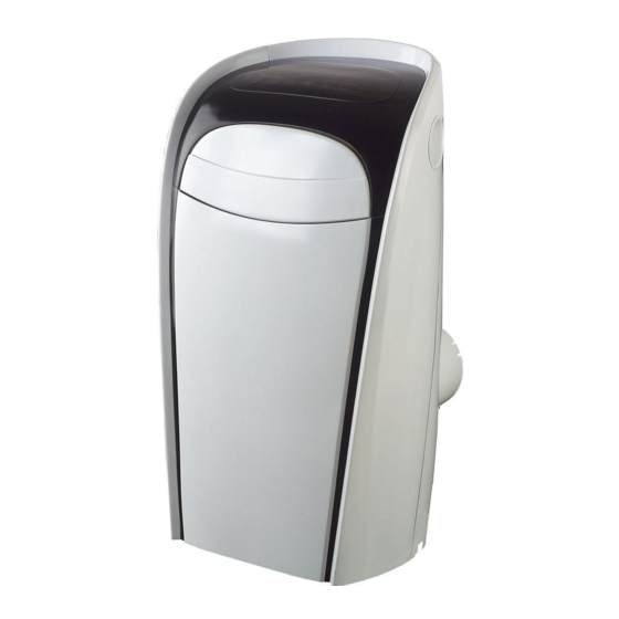
IDENTIFICATION OF PARTS NAMES OF PARTS Front Operation Panel Horizontal Louver Blade (swings automatically) Carrying Handle (both sides) Remote signal receptor Fig.1 Panel Rear Upper Air Filter (Behind the grille) Air Outlet Wheel Air intake Drain Outlet Air intake Lower Air Filter (Behind the grille) Bottom tray drain outlet Fig.2... -
Page 7: Operating Instructions Operating Instructions
OPERATING INSTRUCTIONS Error codes: E1- Room temperature sensor error- FAN peration Unplug the unit and plug it back in. Press the "MODE" button until the If error repeats, call for service. "FAN " indicator light comes on. E2- Evaporator temperature sensor error- Press the "FAN SPEED"... - Page 8 OPERATING INSTRUCTIONS panel will illuminate to indicate it received the signal.It will continue to send this signal until the feature is deactivated by pressing the Follow Me button again. If the unit does not receive any Follow Me signal for 7 minutes, Swing automatically the unit will beep to indicate the Follow Me mode has ended.
-
Page 9: Installation Instructions Location
INSTALLATION INSTRUCTIONS INSTALLATION INSTRUCTIONS Location The air conditioner should be placed on a firm foundation to minimize noise and vibration. For safe and secure positioning, place the unit on a smooth, level floor strong enough to support the unit. The unit has casters for easier transport, but it should only be rolled on smooth, flat surfaces. - Page 10 INSTALLATION INSTRUCTIONS Installation in a double-hung sash window Foam seal A (adhesive type) 1. Cut the foam seal A (adhesive type) to the proper length and attach it to the window stool. Fig.8.Then cut the foam seal B to the proper length and place it on the above foam seal A. Fig.9 Fig.8 2.
- Page 11 INSTALLATION INSTRUCTIONS Installation in a sliding sash window Foam seal A 1. Cut the foam seal(adhesive type) to the proper length and (adhesive type) attach it to the window frame. See Fig.12. 2. Attach the window slider kit to the window stool. Adjust the length of the window slider kit according to the width of Fig.12 window, shorten the adjustable window kit if the width of...
-
Page 12: Exhaust Hose Installation
INSTALLATION INSTRUCTIONS Exhaust hose installation: The exhaust hose and adaptor must be installed or removed in accordance with the usage mode. Fig.16 Fig.17 COOL mode Install Remove FAN or DEHUMIDIIFY mode 1. Install the window Exhaust adaptor B onto the exhaust hose as shown in Fig.16. -
Page 13: Water Drainage
INSTALLATION INSTRUCTIONS Water drainage: During dehumidifying modes, remove the drain Remove the plug from the back of the unit, install the drain drain plug connector (5/8 universal female mender) with 3 4 hose (locally purchased). For the models without drain connector, just attach the drain hose to the hole. -
Page 14: Care And Maintenance
CARE AND MAINTENANCE CARE AND MAINTENANCE IMPORTANT: Upper filter 1) Be sure to unplug the unit before cleaning or servicing. (take out) 2) Do not use gasoline, thinner or other chemicals to clean the unit. 3) Do not wash the unit directly under a tap or using a hose. It may cause electrical danger. -
Page 15: Troubleshooting Tips
TROUBLESHOOTING TIPS TROUBLESHOOTING TROUBLES POSSIBLE CAUSES SUGGEST REMEDIES 1. Unit does not - P1 appears in the display window Drain the water in the bottom tray. start when pressing on/off - Room temperature is lower than Reset the temperature. button the set temperature.(Cooling mode) - The windows or doors in the room Make sure all the windows and... -
Page 16: Remote Controller Illustration
REMOTE CONTROLLER Specifications Model RG09K/BG(C)EF, RG09K/BG(C)EFU, 3.0V(Dry batteries R03/LR03 2) Rated Voltage Lowest Voltage of 2.0V CPU Emitting Signal Transmission Distance 26 ft/8m (36 ft/11m range with 3.0v) Environment -5 C 60 C(-41 F~140 NOTE: Temperature setting display: Celsius scale( C): RG09K/BG(C)EF. - Page 17 REMOTE CONTROLLER FEATURES Remote Controller Features ON/OFF Button : Push this button to start operation, push the button again to stop operation. MODE Select Button: Each time you push the button, a mode is selected in a sequence that goes from AUTO COOL and FAN , as the following figure...
- Page 18 Features of remote control(continued) FOLLOW ME Button : Push this button to initiate the Follow Me feature, the remote display is actual temperature at its location. The rem ote control will send this signal to the air conditioner every 3 minutes interval until press the Follow Me button again.
- Page 19 Indicators on remote controller Tra nsm ission I ndic at or This transmission indicator lights when remote controller transmits signals to the indoor unit. M ode displa y Displays the current operation mode. Including AUTO( ), COOL( ), DRY( ), HEAT( AUTO (Not applicable to cooling only models), FAN ONLY (...
- Page 20 Setting the clock Before you start operating the air conditioner, set the clock of the remote controller using the procedures given in this section. The clock panel on the remote controller will display the time regardless of whether the air conditioner is in use or not. I nit ia l Se t t ing or t he Cloc k After batteries are inserted in the remote controller, the clock panel will display "12:00".
- Page 21 Automatic operation When you set the air conditioner in AUTO mode, it will automatically select cooling, heating (on certain models), or fan only operation depending on what temperature you have selected and the room temperature. Once you select the operating mode, the operating conditions are saved in the unit's microcomputer memory.
- Page 22 Cooling/Heating/Fan only operation St a r t Ensure unit is plugged and power is available. The OPERATION lamp on the display panel of the unit starts flashing. 1. Mode select button (MODE) Press to select COOL, HEAT (on some models only), or FAN ONLY 2.
- Page 23 Timer operation 1. TIMER button Press the TIMER button, the remote displays 0.0 alongside either the TIMER ON or TIMER OFF indicator, and will flash. 2. TEMP/TIME button Press to set the desired time. Forward Backward Press or hold the forward or backward button to change the Auto time by 0.5 hour increments, up to 10 hours, then at 1 hour increments up to 24 hours.
- Page 24 Example of timer setting TIMER ON (Timer Start Operation) The TIMER ON feature is useful when you want the unit to turn on automatically before you return home. The air conditioner will automatically start operating at the set time. IMPORTANT:The time will be registered Start within a 3 second period (after pressing the TEMP/TIME button), so you should...
- Page 25 COMBINED TIMER (Setting both ON and OFF timers simultaneously) TIMER OFF TIMER ON Stop Start operation) This feature is useful when you want to stop the air conditioner after you go to bed, and start it again in the morning when you wake up or when you return home.
- Page 26 Re pla c ing ba t t e rie s The remote controller uses two AA batteries (R03/LR03X2) (1) Slide the cover of the battery compartment off according to the arrow direction, then replace the old batteries with new ones. (2) Insert the new batteries making sure that the(+) and (-) of battery are installed correctly.
-
Page 27: Warranty
WARRANTY Thank you for purchasing this UBERHAUS product. These products have been made to demanding high-quality standards and are guaranteed for domestic use against manufacturing faults for a period of 36 months from the date of purchase. This warranty does not affect your statutory rights.
Need help?
Do you have a question about the MPG-10CRN1-BH9 and is the answer not in the manual?
Questions and answers
Combien de BTU a cet appareil ? MPG-10CRN1-BH9
Bonjour... Je veux avoir un tuyau échappements pour l'air climatisé Modèle 87795001/MPG-10CRN1-BH9