
Subscribe to Our Youtube Channel
Summary of Contents for JUMO CEROS S01 M
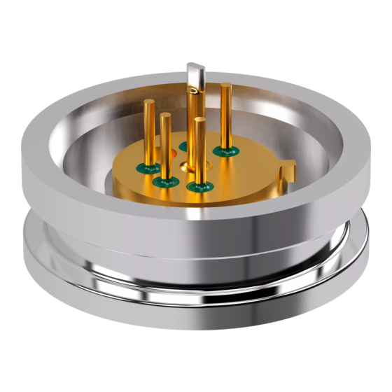
- Page 1 JUMO CEROS S01 M Digital pressure measuring cell Interface Description 40510109T92Z001K000 V4.00/EN/00687084/2020-06-30...
-
Page 3: Table Of Contents
Contents Contents General information and notes for the reader ..... 5 General ..............5 Trademark information . - Page 4 Contents 4.7.1 Sensor configuration ............24 4.7.2 Communication .
-
Page 5: General Information And Notes For The Reader
General information and notes for the reader 1 General information and notes for the reader General This manual contains important information regarding the safe and proper use of this product. Before starting any form of work using this product, this manual must be read and understood. Only by observing all of the safety information and all safety/warning symbols in this manual can opti- mum protection of both personnel and the environment, as well as safe and fault-free operation of the device, be ensured. -
Page 6: Symbols And Signal Words
1 General information and notes for the reader Symbols and signal words 1.3.1 Warning symbols DANGER! The signal word "DANGER" indicates an immediate danger. Non-observance will lead to death or serious injury. The instructions in the warning notice must be observed and followed! WARNING! The signal word "WARNING"... -
Page 7: I²C - Communication
I²C - communication 2 I²C - communication General The digital pressure measuring cell is equipped with a digital I²C interface and optionally an analog out- put. The communication via the I²C interface is described in the following chapters. This includes the correct electrical connection, the entire design as an I²C-bus with master, slave and pull-up resistors. -
Page 8: Entire Design Of The I²C-Bus
2 I²C - communication 2.2.3 Entire design of the I²C-bus The following figure shows a entire design by way of example, including a master, three digital pressure measuring cells as slaves and pull-up resistors. The signal wires SDA and SCL are connected by pull- up resistors to U . -
Page 9: Connection To The Computer
2 I²C - communication 2.2.4 Connection to the computer NOTE! The digital pressure measuring cell can be connected with a PC/Notebook via PC-Interface with Con- verter USB/I²C TO39. see chapter 4.3 "Connection to the computer", Page 19 Bit rate The digital pressure measuring cell works over two sets of bitrates (transfer speed). -
Page 10: Addressing
2 I²C - communication • Valid data Data is transmitted in bytes (8 bits) starting with the most significant bit (MSB). Each byte transmitted is followed by an acknowledge bit. Transmitted bits are valid if, after a start condition, SDA remains at a constant level during the high period of SCL. -
Page 11: Write Operation
2 I²C - communication WRITE Operation An I²C WRITE operation is initiated by the master sending the slave an address byte including a data direction bit set to ‘0’ (WRITE). The address byte is followed by a command byte, and for applicable com- mands two additional data bytes (optional). - Page 12 2 I²C - communication...
-
Page 13: Sensor Data
Sensor data 3 Sensor data Receive sensor data The chart states the combination of address and function in the default settings. ADDR default 0x28 W (Write): 0 ADDR | W default 0x50 R (Read): 1 ADDR | R default 0x51 3.1.1 Pressure... -
Page 14: Read Nvm (Non-Volatile Memory)
3 Sensor data 3.1.3 Read NVM (Non-Volatile Memory) NOTE! The NVM can only be read out in Command Mode. A measured value can only be read out in Normal Mode. Changes of NVM registers have influence on the checksum and the function of the cell and are therefore not allowed! 1. - Page 15 FA number (production order number) highword [31:16] 0x41 FA number (production order number) lowword [15:0] 0x42 Production location – 010 (dec) for JUMO Fulda 0x43 Production date – year [15:8] / calendar week [7:0] 0x44 Counter number (serial number) 000 to 999...
-
Page 16: Interpretation Of The Sensor Data
3 Sensor data Interpretation of the sensor data 3.2.1 Pressure The conversion of the digital values to decimal pressure values is realized by a linear function defined by two points (P and P P[u15] P[bar] P[bar] example : 3277 (10 % of 15 bit) : 29491 (90 % of 15 bit) The minimum and maximum pressure values are stated in the order confirmation. -
Page 17: Temperature
3 Sensor data 3.2.2 Temperature The interpretation of the digital temperature values follows a linear function. To interpret the digital values of the temperature it is necessary to read the parameters T and T once from NVM (0x45 and slope offset 0x46), by using the commands (... - Page 18 3 Sensor data...
-
Page 19: Pc Software
NOTE! The PC software was developed for communication between PC and digital pressure measuring cell and is available as a free download at www.jumo.net. 1. Start the installation file after the download via Windows Explorer. 2. Follow the installation instructions. -
Page 20: Program Start
4 PC software Program start Windows Start Menu 1. Make sure the digital pressure cell is connected to the PC/notebook. see chapter 4.3 "Connection to the computer", Page 19 2. Start the PC software via the Windows Start Menu. The start screen of the PC software appears. -
Page 21: Measuring
4 PC software Measuring 4.5.1 Connecting with sensor 1. Connect the digital pressure measuring cell to the PC software via the button in the Sensor - Quick info window. After successfully connecting the digital pressure measuring cell and PC software, Part number (1) and Serial number (2) of the sensor are displayed in the Sensor - Quick info window. -
Page 22: Sensor Information
4 PC software Sensor information The Sensor information dialogue box displays non-editable information about the digital pressure mea- suring cell. The information is used to uniquely identify the digital pressure measuring cell. 4.6.1 Sensor details The individual parameters Temperature slope (4) and Temperature offset (5) are displayed in the Sen- sor details tab (1). -
Page 23: Versions
4 PC software 4.6.2 Versions The individual product details Product Version (4), Production number (3) and Chip position (2) are displayed in the Versions tab (1) which is used for traceability of the digital pressure measuring cell. -
Page 24: Configuration
4 PC software Configuration The Configration dialogue box displays editable information and sensor data about the digital pressure measuring cell. 4.7.1 Sensor configuration The Sensor configuration tab (1) displays editable functions of the analog output of the digital pressure measuring cell see "Measuring range delimitation analog output ", Page 25 (3) and "Process diagno- sis analog output ", Page 26 (4). - Page 25 4 PC software Measuring range delimitation analog output The Lower pressure limit (1) and Upper pressure limit (2) text fields allow to set the Measuring range delimitation of the analog output. Example: NOTE! If changes have been made, the data must be transferred to the sensor via the Write sensor button.
- Page 26 4 PC software Process diagnosis analog output To use the Diagnosis mode (1), you can choose either a 0 V or 5 V output signal of the analog output. Overload limits If the Diagnosis mode is not deactivated, analog output enters the choosen diagnosis mode by exceed the overload limits.
- Page 27 4 PC software To use the Diagnosis mode (1), you can choose either a 0 V or 5 V output signal of the analog output. Temperature limits If the Diagnosis mode is not deactivated, analog output enters the choosen diagnosis mode by exceed the temperature limits.
-
Page 28: Communication
4 PC software 4.7.2 Communication The Communication tab (1) displays the I²C Standard address (4). The sensor always responds to the standard address. The drop-down menu Optional Address (2) allows the selection of further addresses and transferring them to the digital pressure measuring cell via the Write sensor button (3). To the optional addresses the digital pressure measuring cell responds as a slave. -
Page 29: Calibration
4 PC software Calibration The Calibration dialogue box displays current sensor values and offers performing an offset correc- tion. 4.8.1 Offset correction In order to increase the accuracy in the operating point, the Offset correction tab (1) offers performing offset correction at any operating point by specifying a reference pressure (2) and pushing the button. -
Page 30: Settings
4 PC software Settings Via the Settings menu the Default settings dialogue box can be edited. NOTE! Changing the language will only be effective after a fresh program start! -
Page 31: Info
4 PC software 4.10 Info Via the Info menu, information about the setup software can be called up. NOTE! In case of service or maintenance, please have this information ready. -
Page 32: Error Messages
4 PC software 4.11 Error messages Error cause: Digital pressure measuring cell is not connected to the computer Troubleshooting: Connect the digital pressure measuring cell with the USB port of your PC/Notebook by using PC-Interface with Converter USB/I²C TO39 (Part no. 00695325) More information: ... - Page 34 JUMO GmbH & Co. KG JUMO Instrument Co. Ltd. JUMO Process Control, Inc. Street address: JUMO House 6733 Myers Road Moritz-Juchheim-Straße 1 Temple Bank, Riverway East Syracuse, NY 13057, USA 36039 Fulda, Germany Harlow, Essex, CM20 2DY, UK Delivery address:...
Need help?
Do you have a question about the CEROS S01 M and is the answer not in the manual?
Questions and answers