Table of Contents
Advertisement
Quick Links
®
This publication contains the installation, operation
and maintenance instructions for standard units of the
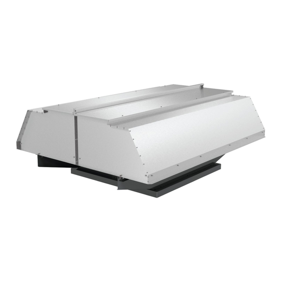
H-Series: Hooded Propeller Roof Fans.
• HEE/HES
• HEF
• HER
• HXE/HXS
Carefully read this publication and any
supplemental documents prior to any
installation or maintenance procedure.
Loren Cook catalogs, H-Series Belt Drive and H-Series
Direct Drive, provide additional information describing the
equipment, fan performance, available accessories and
specification data.
For additional safety information, refer to AMCA Publi-
cation 410-96, Safety Practices for Users and Installers of
Industrial and Commercial Fans.
All of the publications listed above can be obtained from:
• lorencook.com
• info@lorencook.com
• 417-869-6474 ext. 166
For information and instructions on special equipment,
contact Loren Cook Company at 417-869-6474.
Receiving and Inspection
Carefully inspect the fan and accessories for any dam-
age and shortage immediately upon receipt of the fan. The
control panel, if ordered, is shipped inside of the roof base.
It is not counted as a separate part.
• Turn the propeller by hand to ensure it turns freely and does
not bind
• Check the dampers (if included) for free operation of all
moving parts
• Record on the Delivery Receipt any visible sign of damage
H-Series
Handling
Lift the fan by the base.
NOTICE! Never lift by the shaft, motor or housing. If
your fan has a special protective finish, handle with
extreme care. Even a small chip will break the coating's
continuity and destroy its ability to protect the metal.
Propellers are carefully balanced to give smooth, vibra-
tion-free operation. If the propeller is damaged during han-
dling, it will require rebalancing.
H-SERIES IO&M
INSTALLATION, OPERATION AND MAINTENANCE MANUAL
• HXF
• HEE-D/HES-D
• HEF-D
• HER-D
Rotating Parts & Electrical Shock Hazard:
Fans should be installed and serviced by qualified person-
nel only.
Disconnect electric power before working on unit (prior to
removal of guards or entry into access doors).
Follow proper lockout/tagout procedures to ensure the unit
cannot be energized while being installed or serviced.
A disconnect switch should be placed near the fan in order
that the power can be swiftly cut off, in case of an emer-
gency and in order that maintenance personnel are pro-
vided complete control of the power source.
Grounding is required. All field-installed wiring must be
completed by qualified personnel. All field installed wiring
must comply with National Electric Code (NFPA 70) and all
applicable local codes.
Fans and blowers create pressure at the discharge and
vacuum at the inlet. This may cause objects to get pulled
into the unit and objects to be propelled rapidly from the
discharge. The discharge should always be directed in a
safe direction and inlets should not be left unguarded. Any
object pulled into the inlet will become a projectile capable
of causing serious injury or death.
When air is allowed to move through a non-powered fan,
the impeller can rotate, which is referred to as windmill-
ing. Windmilling will cause hazardous conditions due to
unexpected rotation of components. Impellers should be
blocked in position or air passages blocked to prevent draft
when working on fans.
Friction and power loss inside rotating components will
cause them to be a potential burn hazard. All components
should be approached with caution and/or allowed to cool
before contacting them for maintenance.
Under certain lighting conditions, rotating components
may appear stationary. Components should be verified to
be stationary in a safe manner, before they come into con-
tact with personnel, tools or clothing.
Failure to follow these instructions could result in death or
serious injury.
The attachment of roof mounted fans to the roof curb as
well as the attachment of roof curbs to the building struc-
ture must exceed the structural requirements based on the
environmental loading derived from the applicable build-
ing code for the site. The local code official may require
variations from the recognized code based on local data.
The licensed engineer of record will be responsible for pre-
scribing the correct attachment based on construction ma-
terials, code requirements and environmental effects spe-
cific to the installation.
1
H-SERIES
Hooded Propeller Roof Fans
B51051-003
Advertisement
Table of Contents

Related Manuals for Loren Cook H Series


Summary of Contents for Loren Cook H Series
- Page 1 Follow proper lockout/tagout procedures to ensure the unit installation or maintenance procedure. cannot be energized while being installed or serviced. Loren Cook catalogs, H-Series Belt Drive and H-Series A disconnect switch should be placed near the fan in order Direct Drive, provide additional information describing the...
-
Page 2: Installation
Storage Typical Damper Motor Schematic If the fan is stored for any length of time prior to installa- tion, store it in its original shipping crate and protect it from Motor dust, debris and the weather. Outdoor Storage To maintain good working condition of the fan when it is stored outdoors or at a construction site, follow the instruc- Transformer** Transformer**... -
Page 3: Damper Installation
Damper Installation Figure 2 OFFSET ANGULAR OFFSET/ANGULAR If your fan is supplied with dampers, follow the directions below. If your fan does not include dampers, proceed to Motor Installation. 1. Place the damper inside the curb. Ensure the damper will open freely for the correct direction of the airflow. CENTER Tolerance 2. -
Page 4: Operation
Fan Installation Do not allow the fan to run in the wrong direction. This will overheat the motor and cause serious The fan support (roof curb) should provide a level sur- dam-age. For 3-phase motors, if the fan is running face for installation. -
Page 5: Maintenance
Should the motor prove defective within a one-year pe- The fan bearings are provided prelubricated. Any special- riod, contact your local Loren Cook representative or your ized lubrication instructions on fan labels supersedes in- nearest authorized electric motor service representative. -
Page 6: Bearing Replacement
Speed Reduction the shaft. Remove the bearing from the shaft using a bearing Open the pulley in order that the belt rides deeper in the puller. groove (smaller pitch diameter). 8. Install the pulley in the correct location on the shaft Speed Increase Secure the bearing hold-down bolts, but do not fully Close the pulley in order that the belt rides higher in the... -
Page 7: Troubleshooting
Troubleshooting HEE-D/HES-D/HER-D Parts List Problem and Potential Cause Low Capacity or Pressure: • Incorrect direction of rotation. Make sure the fan rotates in same direction as the arrows on the motor or belt drive assembly • Poor fan inlet conditions. There should be a straight clear duct at the inlet •... -
Page 8: Limited Warranty
Cook Company, General Offices, 2015 East Dale Street, Springfield, Missouri 65803-4637, explaining in writing, in detail, your complaint and referring to the specific model and serial numbers of your fan. Upon receipt by Loren Cook Company of your written complaint, you will be notified, within thirty (30) days of our receipt of your complaint, in writing, as to the manner in which your claim will be handled.
Need help?
Do you have a question about the H Series and is the answer not in the manual?
Questions and answers