Table of Contents
Advertisement
Quick Links
®
This publication contains the installation, operation
and maintenance instructions for standard units of the
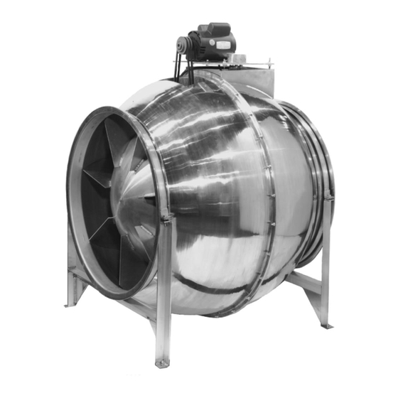
CV: Centri-Vane
Aluminum Inline and Roof Fans.
®
• CVD
• CVB
• CVR
Carefully read this publication and any
supplemental documents prior to any
installation or maintenance procedure.
Loren Cook catalog, CV, provides additional information
describing the equipment, fan performance, available
accessories and specification data.
For additional safety information, refer to AMCA Publica-
tion 410-96, Safety Practices for Users and Installers of
Industrial and Commercial Fans.
All of the publications listed above can be obtained from:
• lorencook.com
• info@lorencook.com
• 417-869-6474 ext. 166
For information and instructions on special equipment,
contact Loren Cook Company at 417-869-6474.
Receiving and Inspection
Carefully inspect the unit and accessories for any dam-
age and shortage immediately upon receipt of the unit.
• Turn the propeller by hand to ensure it turns freely and
does not bind.
• Record on the Delivery Receipt any visible sign of damage.
Handling
Lift the fan by the outside housing and support leg.
NOTICE! Never lift by the shaft, motor or housing.
CVB
Storage
If the fan is stored for any length of time prior to installa-
tion, store it in its original shipping crate and protect it from
dust, debris and weather.
CV IO&M
INSTALLATION, OPERATION AND MAINTENANCE MANUAL
• CVR-S
• CV/UCV-S
• CVS
Centri-Vane
Rotating Parts & Electrical Shock Hazard:
Fans should be installed and serviced by qualified person-
nel only.
Disconnect electric power before working on unit (prior to
removal of guards or entry into access doors).
Follow proper lockout/tagout procedures to ensure the unit
cannot be energized while being installed or serviced.
A disconnect switch should be placed near the fan in order
that the power can be swiftly cut off, in case of an emergen-
cy and in order that maintenance personnel are provided
complete control of the power source.
Grounding is required. All field-installed wiring must be
completed by qualified personnel. All field installed wiring
must comply with National Electric Code (NFPA 70) and all
applicable local codes.
Fans and blowers create pressure at the discharge and
vacuum at the inlet. This may cause objects to get pulled
into the unit and objects to be propelled rapidly from the
discharge. The discharge should always be directed in a
safe direction and inlets should not be left unguarded. Any
object pulled into the inlet will become a projectile capable
of causing serious injury or death.
When air is allowed to move through a non-powered fan,
the impeller can rotate, which is referred to as windmill-
ing. Windmilling will cause hazardous conditions due to
unexpected rotation of components. Impellers should be
blocked in position or air passages blocked to prevent draft
when working on fans.
Friction and power loss inside rotating components will
cause them to be a potential burn hazard. All components
should be approached with caution and/or allowed to cool
before contacting them for maintenance.
Under certain lighting conditions, rotating components may
appear stationary. Components should be verified to be
stationary in a safe manner, before they come into contact
with personnel, tools or clothing.
Failure to follow these instructions could result in death or
serious injury.
The attachment of roof mounted fans to the roof curb as
well as the attachment of roof curbs to the building struc-
ture must exceed the structural requirements based on the
environmental loading derived from the applicable building
code for the site. The local code official may require varia-
tions from the recognized code based on local data. The
licensed engineer of record will be responsible for prescrib-
ing the correct attachment based on construction materi-
als, code requirements and environmental effects specific
to the installation.
1
Aluminum Inline and Roof Fans
®
CV
B51161-003
Advertisement
Table of Contents

Related Manuals for Loren Cook Centri-Vane CV Series


Summary of Contents for Loren Cook Centri-Vane CV Series
- Page 1 Follow proper lockout/tagout procedures to ensure the unit installation or maintenance procedure. cannot be energized while being installed or serviced. Loren Cook catalog, CV, provides additional information A disconnect switch should be placed near the fan in order describing the equipment, fan performance, available that the power can be swiftly cut off, in case of an emergen- accessories and specification data.
-
Page 2: Wiring Installation
To maintain good working condition of a CV when it is Figure 2 OFFSET ANGULAR OFFSET/ANGULAR stored outdoors, or on a construction site, follow the addi- tional steps below: Tolerance • Cover the inlet and outlet, and belt tunnel opening to prevent Center Maximum the accumulation of dirt and moisture in the housing... -
Page 3: Wiring Diagrams
Wiring Diagrams 2 Speed, 2 Winding, 3 Phase Single Speed, Single Phase Motor Low Speed Low Speed Ground A Low Speed Line Motor High Speed High Speed Line High Speed To reverse: High Speed - interchange leads T and T Ground B Low Speed - interchange leads T and T... -
Page 4: Maintenance
Motor bear- Lubricants ings without provisions for relubrication will operate up to Loren Cook Company uses petroleum lubricant in a lith- 10 years under normal conditions with no maintenance. In ium base conforming to NLGI grade 2 consistency. Other... -
Page 5: Bearing Replacement
Should the motor prove defective within a one-year pe- The fan bearings are flange ball bearings. riod, contact your local Loren Cook representative or your 1. Loosen the motor plate adjustment bolts, then slide nearest authorized electric motor service representative. -
Page 6: Troubleshooting
Troubleshooting Parts List Problem and Potential Cause Low Capacity or Pressure: • Incorrect direction of rotation. Make sure the fan rotates in same direction as the arrows on the motor or belt drive assembly • Poor fan inlet conditions. There should be a straight clear duct at the inlet •... - Page 7 CVR-S Air Flow Part No. Part Description (Sizes 12-36) Belt Set Motor Plate Motor Outer Discharge Housing Belt Air Flow Outer Inlet Housing Wheel Assembly Part No. Part Description (Sizes 10-36) Bearings Topcap Assembly Shaft Post Mounting Feet Wheel Assembly Motor Plate Saddle Motor Plate Motor...
-
Page 8: Limited Warranty
Cook Company, General Offices, 2015 East Dale Street, Springfield, Missouri 65803-4637, explaining in writing, in detail, your complaint and referring to the specific model and serial numbers of your fan. Upon receipt by Loren Cook Company of your written complaint, you will be notified, within thirty (30) days of our receipt of your complaint, in writing, as to the manner in which your claim will be handled.
Need help?
Do you have a question about the Centri-Vane CV Series and is the answer not in the manual?
Questions and answers