Loren Cook ACE-D Installation, Operation And Maintenance Manual

Loren Cook ACE-D Installation, Operation And Maintenance Manual

Centrifugal roof and wall exhausters

Advertisement

®
This publication contains the installation, operation and
maintenance instructions for standard units of the AC-
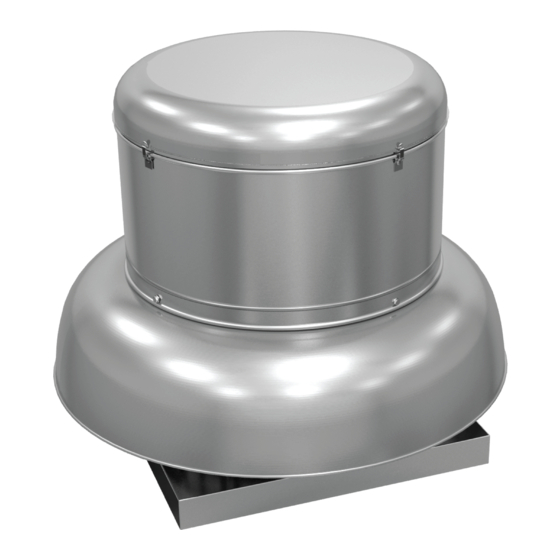
Centrifugal Roof and Wall Exhausters.
• ACE-D / ACE-B
• ACW-D / ACW-B / ACW-HP / ACW-XP
• ACRU-D / ACRU-B / ACRU-HP / ACRU-XP
Carefully read this publication and any
supplemental documents prior to any
installation or maintenance procedure.
Loren Cook AC catalog provides additional information
describing the equipment, fan performance, available
accessories, and specification data.
For additional safety information, refer to AMCA
publication 410-96, Safety Practices for Users and Installers
of Industrial and Commercial Fans.
All of the publications listed above can be obtained from
Loren Cook Company by phoning (417)869-6474,
extension 166; by FAX at (417)832-9431; or by e-mail at
info@lorencook.com.
For information and instructions on special equipment,
contact Loren Cook Company at 417.869-6474.
Rotating Parts & Electrical Shock Hazard:
Disconnect electric power before working on unit.
Follow proper lockout / tagout procedures to ensure
the unit cannot be energized while being installed or
serviced.
A disconnect switch should be placed near the fan in
order that the power can be swiftly cut off, in case of
an emergency and in order that maintenance
personnel are provided complete control of the power
source.
Grounding is required. All field-installed wiring must
be completed by qualified personnel. All field-
installed wiring must comply with National Electric
Code (NFPA 70) and all applicable local codes.
Failure to follow these instructions could result in
death or serious injury.
Receiving and Inspection
Immediately upon receipt of an AC fan, carefully inspect
the fan and accessories for damage and shortage.
• Turn the wheel by hand to ensure it turns freely and
does not bind.
• Check dampers (if included) for free operation of all
moving parts.
• Record on the Delivery Receipt any visible sign of
damage.
INSTALLATION, OPERATION AND MAINTENANCE
Handling
Lift the fan by the shipping
carton or lifting lugs provided
under top cap. NOTICE! Never
lift by the shaft, motor or
housing.
Storage
If the fan is stored for any
length of time prior to installation,
store it in its original shipping
crate and protect it from dust,
debris and the weather.
Installation
If the fan was delivered with the motor unmounted, see
the maintenance section for belt and pulley installation.
If the fan was purchased as a wall mount unit and a
grease terminator or grease trough was not purchased, a 1-
1/16 inch diameter drain hole should be drilled at the bottom
side of the fan for drainage.
Code requirements and environmental effects
The attachment of roof mounted fans to the roof curb
as well as the attachment of roof curbs to the building
structure must exceed the structural requirements
based on the environmental loading derived from the
applicable building code for the site. The local code
official may require variations from the recognized
code based on local data. The licensed engineer of
record will be responsible for prescribing the correct
attachment based on construction materials, code
requirements and environmental effects specific to
the installation.
Failure to follow these instructions could result in
death or serious injury.
Centrifugal Roof and Wall Exhausters
AC
Lifting Lugs

Advertisement

Table of Contents
loading
Need help?

Need help?

Do you have a question about the ACE-D and is the answer not in the manual?

Questions and answers

Summary of Contents for Loren Cook ACE-D

  • Page 1 If the fan is stored for any installation or maintenance procedure. length of time prior to installation, Loren Cook AC catalog provides additional information store it in its original shipping describing the equipment, fan performance, available crate and protect it from dust, accessories, and specification data.
  • Page 2: Damper Installation

    Wall Exhauster Installation the ventilator base to the motor compartment. For external wiring, run the wires through the horizontal If your fan is a wall exhauster, a mounting template is conduit on upblast units, or under top cap in downblast shipped with the fan.
  • Page 3: Operation

    7. Ensure fan and ductwork are clean and free of debris. Typical Damper Motor Schematic 8. Close and secure all access doors. 9. Restore power to fan. Motor Start-up Turn on the fan. In variable speed units, set the fan to its lowest speed.
  • Page 4: Fan Bearings

    Bearings should be relubricated in accordance with the Motor Services condition chart below. Should the motor prove defective within a one-year period, Conditions Chart contact your local Loren Cook representative or your nearest Temp °F Greasing Interval authorized electric motor service representative. -30 to 120...
  • Page 5: Pulley Alignment

    Pulley Alignment Replacing Pulleys and Belts Pulley alignment is adjusted by 1. Clean the motor and fan shafts. loosening the motor pulley 2. Loosen the motor plate mounting bolts to relieve the belt setscrew and by moving the motor tension. Remove the belt. pulley on the motor shaft.
  • Page 6: Troubleshooting

    Troubleshooting Recommended Puller: Lisle No. 45000 Sterling Wheel Puller. This puller is available at most automotive parts retail outlets. Problem and Potential Cause Low Capacity or Pressure •Incorrect direction of rotation. Make sure the fan rotates in same direction as the arrows on the motor or belt drive assembly. •Poor fan inlet conditions.
  • Page 7 ACE-D Parts List ACE-D Parts Description Part 70-100 120-180 Top Cap Lid Top Cap Top Cap Cylinder — Top Cap Clip (4) Motor Motor Motor Plate Motor Plate Baffle Baffle Wheel Assembly Wheel Assembly Bird Screen Bird Screen Base Base...
  • Page 8 ACE-B Parts List ACE-B Parts Description Part 60-100 120-245 270-300 330-540 Top Cap Lid Top Cap Lid Top Cap Lid Top Cap Lid Top Cap Cylinder Top Cap Cylinder Top Cap Cylinder Top Cap Cylinder Top Cap Clip (4) Top Cap Clip (4) Top Cap Clip (8) Top Cap Clip (8) Motor Motor...
  • Page 9 ACW-D Parts List ACW-D Parts Description Part 70-100 120-195 Top Cap Lid Top Cap Top Cap Cylinder — Top Cap Clip (4) Motor Motor Motor Plate Spun Motor Plate Baffle Baffle Wheel Assembly Wheel Assembly Bird Screen Bird Screen Wall Flange Wall Flange Post (4) Post (4)
  • Page 10 ACW-B Parts List ACW-B Parts Description Part 120-165 180-245 Top Cap Lid Top Cap Lid Top Cap Clip Top Cap Cylinder Top Cap Cylinder Top Cap Cylinder Top Cap Clip (4) Top Cap Clip (4) Top Cap Clip (4) Motor Motor Motor Spun Motor Plate...
  • Page 11 ACRU-D Parts List ACRU-D Parts Description Part 70-100 120-195 Top Cap Lid Top Cap Top Cap Cylinder — Top Cap Clip (4) Motor Motor Motor Plate Spun Motor Plate Baffle Baffle Wheel Assembly Wheel Assembly Bird Screen Bird Screen Base Base Conduit Conduit...
  • Page 12 To make a warranty claim, notify Loren Cook Company, General Offices, 2015 East Dale Street, Springfield, Missouri 65803-4637, explaining in writing, in detail, your complaint and referring to the specific model and serial numbers of your fan. Upon receipt by Loren Cook Company of your written complaint, you will be notified, within thirty (30) days of our receipt of your complaint, in writing, as to the manner in which your claim will be handled.

Table of Contents

Save PDF