Table of Contents
Advertisement
Quick Links
Advertisement
Table of Contents

Subscribe to Our Youtube Channel
Related Manuals for SystemAir S-BM2


Summary of Contents for SystemAir S-BM2
- Page 1 Fire Safety Products S-BM2 Smoke Control Damper - MA Multi User Manual...
-
Page 2: Table Of Contents
Installation Distances ....10 Manipulation of S-BM2 ....11 Wet Installation . -
Page 3: Introduction
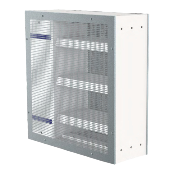
202010 | User Manual S-BM2 | 3/48 Introduction This is the original installation, inspection and operating instructions document for the S-BM2 smoke control damper. EVERY S-BM2 SMOKE CONTROL DAMPER NEEDS TO BE INSTALLED IN ACCORDANCE WITH THIS DOCUMENT! S-BM2 Multiblade smoke control damper with or without mesh for installations in the wall, on the vertical or horizontal duct. -
Page 4: Warnings
4/48 | User Manual S-BM2 | 202010 Warnings Some damper parts may have sharp edges – therefore, to protect yourself from harm, please use gloves during damper installation and manipulation. In order to prevent electric shock, fire or any other damage which could result from incorrect damper usage and operation, it is important to: 1. -
Page 5: Installation
The distance between smoke control damper and the adjacent wall/ceiling and the smoke control damper must be at least 75 mm. • When the S-BM2 smoke control damper is installed into a smoke and fire partition structure, it must be placed so that the damper blades in its closed position are located inside this structure. •... -
Page 6: Installation Methods
6/48 | User Manual S-BM2 | 202010 Installation Methods S-BM2 Smoke control dampers are CE certified following the Construction Products Regulation according to EN 12101-8:2011. Tested according to EN 1366-10:2011 + A1:2017, EN 1366-2:2015 and classified according to EN 13501-4:2016. - Page 7 202010 | User Manual S-BM2 | 7/48 Legend Wet Installation Dry Installation Fit Installation Damper placed on duct surface, bottom side of the duct Damper placed on duct surface, top side of the duct Damper placed on duct surface, left and right side of the duct...
-
Page 8: Opening Preparation For S-Bm2 Installation
8/48 | User Manual S-BM2 | 202010 Opening Preparation for S-BM2 Installation The S-BM2 smoke control damper can be installed in a supporting construction between zones classified as “multi-multi”, “multi-single” and “single-multi”. Opening Preparation for a Rigid Wall Fig. 1: Rigid wall/ceiling with a rectangular opening... - Page 9 202010 | User Manual S-BM2 | 9/48 Opening Preparation for a Flexible Wall Fig. 2: Flexible (plasterboard) wall with a rectangular opening and vertical cross-section (right) Legend On each side - 2 layers of plasterboard fireproof plate type F, EN 520 (thickness see Tab. 4) Vertical CW-profiles (profiles with s based on fire resistivity, see Tab.
-
Page 10: Installation Distances
10/48 | User Manual S-BM2 | 202010 Installation Distances According to the EN 1366-2 standard, the minimum distance from the wall or ceiling to the damper body is 75 mm. For multiple crossings through a fire resistive wall, the minimum distance between two damper bodies is 200 mm. -
Page 11: Manipulation Of S-Bm2
Manipulation of S-BM2 The S-BM2 is made of boards and can thus be considered fragile. Handling and manipulation must be done with care. Smaller dimensions can be manipulated and placed in the installation opening by two persons. Bigger dimensions are supplied with wooden blocks, those serve as support for suitable lifting equipment (forklift, crane). - Page 12 12/48 | User Manual S-BM2 | 202010 Y₂ Fig. 6: Carefully lift the smoke control damper with the forklift, crane. NOTE: Y = Cutting plane Fig. 7: Prepare the opening, damper hanger, connection surfaces and/or filling as per the desired installation type...
- Page 13 202010 | User Manual S-BM2 | 13/48 Y₃ Fig. 8: Once the smoke control damper has been placed fix the damper to ductwork: a) For wall installation - insert the filling as per desired installation. b) For duct installation – fix the hangers so that the weight of the damper is supported.
-
Page 14: Wet Installation
2. Insert the closed damper as per the “Manipulation of S-BM2” section into the middle of the opening so that the damper blade is in the wall. For damper widths greater than 600 mm, it is recommended to use a duct support inside the damper during installation to avoid any damage caused to the damper housing by the weight of the filling. - Page 15 202010 | User Manual S-BM2 | 15/48 Fig. 11: Wet installation of S-BM2 smoke control damper...
- Page 16 16/48 | User Manual S-BM2 | 202010 Legend Cross-section of Wet installation in flexible wall (aligned on the outside) Cross-section of Wet installation in rigid wall (aligned on the outside) Cross-section of Wet installation in flexible wall (aligned on the inside)
- Page 17 202010 | User Manual S-BM2 | 17/48 Y₅ 12,5 Y₆ ≥50 ≥10 ≥10 ≥50 Y₇ Y₈ 12,5 ≥50 Y₉ ≥10 ≥10...
-
Page 18: Dry Installation
2. Insert the damper as per the “Manipulation of S-BM2” section into the middle of the opening so that the damper blade is in the wall. For damper widths greater than 600 mm, it is recommended to use a duct support inside the damper during installation to avoid any damage caused to the damper housing by the weight of the filling. - Page 19 202010 | User Manual S-BM2 | 19/48 Fig. 12: Dry installation of S-BM2 smoke control damper...
- Page 20 20/48 | User Manual S-BM2 | 202010 Legend Cross-section of Dry installation in flexible wall (aligned on the outside) Cross-section of Dry installation in rigid wall (aligned on the outside) Cross-section of Dry installation in flexible wall (aligned on the inside)
- Page 21 202010 | User Manual S-BM2 | 21/48 12,5 Y₅ 12,5 ≥50 ≥50 Y₆ ≥10 ≥10 ≥50 Y₇ Y₈ 12,5 Y₉ 12,5 ≥50 ≥50 ≥10 ≥10...
-
Page 22: Fit Installation
2. Insert the closed damper as per the “Manipulation of S-BM2” section into the middle of the opening so that the damper blade is in the wall. For damper widths greater than 600 mm, it is recommended to use a duct support inside the damper during installation to avoid any damage caused to the damper housing by the weight of the filling. - Page 23 202010 | User Manual S-BM2 | 23/48 Fig. 13: Fit installation of S-BM2 smoke control damper...
- Page 24 24/48 | User Manual S-BM2 | 202010 Legend Cross-section of Fit installation in flexible wall (aligned on the outside) Cross-section of Fit installation in flexible wall (aligned on the inside) Cross-section of Fit installation in flexible wall ended with grille (aligned on the outside)
- Page 25 202010 | User Manual S-BM2 | 25/48 Y₃ 12,5 ≥50 ≥50 Y₄ ≥50 ≥10 ≥10 ≥50 12,5 ≥50 ≥50 Y₅ ≥10 ≥10...
-
Page 26: Installation In The Duct Made Of Promatect Boards
S-BM2 smoke control damper can be installed on “single” (tested according to EN 1366-9) or “multi” (tested according to EN 1366-8) ductwork. If mounted on a duct classified with lover fire resistivity, the fire resistivity of S-BM2 smoke control damper will be decreased to the duct level. This section does not depict duct hanger rules as those are dependent on the weight of the duct itself and must be statically approved. - Page 27 202010 | User Manual S-BM2 | 27/48 Fig. 14: Connection of the S-BM2 smoke control damper to board made duct...
- Page 28 Legend Cross-section of duct connection in the mechanism area Cross-section of connection to 30 mm thick board duct Cross-section of connection to 40 mm thick board duct Cross-section of connection to 50 mm thick board duct with the K1-S-BM2 accessory...
- Page 29 202010 | User Manual S-BM2 | 29/48 X₁ Y₁ ≥50 ≥50 ≥30 H × W Y₂ Y₃ ≥50 ≥50 ≥50 ≥50 ≥50 ≥50...
-
Page 30: Installation In The Duct Made Of Sheet Metal
S-BM2 smoke control damper can be installed on “single” (tested according to EN 1366-9) or “multi” (tested according to EN 1366-8) ductwork. If mounted on a duct classified with lover fire resistivity, the fire resistivity of S-BM2 smoke control damper will be decreased to the duct level. This section does not depict duct hanger rules as those are dependent on the weight of the duct itself and must be statically approved. - Page 31 202010 | User Manual S-BM2 | 31/48 Fig. 15: Connection of the S-BM2 smoke control damper to sheet metal ductwork...
- Page 32 32/48 | User Manual S-BM2 | 202010 Follow the instructions and perform the installation as depicted in the figures and the details section. 1. Prepare the duct connection, clean and flatten the connecting surface. 2. Apply fire resistive coat (6) on the connection surfaces.
- Page 33 202010 | User Manual S-BM2 | 33/48 Y₁ Y₂ Y₃ Y₄ ≥50 ≥50 ≥50 ≥10...
-
Page 34: Installation On The Horizontal Duct
S-BM2 smoke control damper can be installed on “single” (tested according to EN 1366-9) or “multi” (tested according to EN 1366-8) ductwork. If mounted on a duct classified with lover fire resistivity, the fire resistivity of S-BM2 smoke control damper will be decreased to the duct level. This section is not depicting duct hanger rules as those are dependent on the weight of the duct itself and must be statically approved. - Page 35 202010 | User Manual S-BM2 | 35/48 Fig. 16: Installation of the S-BM2 smoke control damper Fig. 17: Installation of the S-BM2 smoke control damper on the horizontal duct (flush with edges) on the horizontal duct (surface)
- Page 36 Dimension of opening must be created according to details of each type and thickness of connected duct. The fire resistivity of S-BM2 smoke control damper must be decreased to the duct performance. The maximum resistivity for D1H, D2H installation is EI120S with pressure level 2 (-1000 Pa … 300 Pa)
- Page 37 202010 | User Manual S-BM2 | 37/48 X₁ (D1H, D2H) Y₁ (D1H) ≥50 H × W Y₂ (D1H) (D2H) ≥50 ≥50 ≥30...
-
Page 38: Installation On The Vertical Duct
S-BM2 smoke control damper can be installed on “single” (tested according to EN 1366-9) or “multi” (tested according to EN 1366-8) ductwork. If mounted on a duct classified with lover fire resistivity, the fire resistivity of S-BM2 smoke control damper will be decreased to the duct level. This section is not depicting duct hanger rules as those are dependent on the weight of the duct itself and must be statically approved. - Page 39 202010 | User Manual S-BM2 | 39/48 Fig. 18: Installation of the S-BM2 smoke control damper Fig. 19: Installation of the S-BM2 smoke control damper on the vertical duct (flush with edges) on the vertical duct (surface)
- Page 40 Dimension of opening must be created according details of each type and thickness of connected duct. The fire resistivity of S-BM2 smoke control damper must be decreased to the duct performance. The maximum resistivity for D1V, D2V installation is EI120S with pressure level 2 (-1000 Pa … 300 Pa)
- Page 41 202010 | User Manual S-BM2 | 41/48 X₁ (D1V) X₂ (D1V) ≥30 H × W (H+80) × (W+80) (D2V) Y₁ (D1V, D2V) ≥30 H × W...
-
Page 42: Electrical Connections
Switch off the power supply before working on any electrical equipment. Only qualified electricians are allowed to work on the electrical system. Tab. 5: Electric parameters of Belimo mechanism types (B230; B24) for S-BM2 based on the size Consumption per: Type/... - Page 43 202010 | User Manual S-BM2 | 43/48 AC 230 V AC/DC 24 V ⊥ – S1 S2 S3 S4 S5 S6 S1 S2 S3 S4 S5 S6 <3° <3° <87° <87° Fig. 20: B230 connection scheme; actuator BELIMO Fig. 21: B24 connection scheme; actuator BELIMO...
-
Page 44: Operation Manual
44/48 | User Manual S-BM2 | 202010 Operation Manual After installation, it is necessary to adjust the damper into its operating position “closed”. In case, that the damper is used for extraction of pollutants, adjust the damper into its operating position “open”. -
Page 45: Warranty Conditions
Warranty Conditions For warranty conditions, contact your local Systemair representative. Functionality of every S-BM2 smoke control damper is tested in the production factory before being shipped. Before you can install the fire damper, its functionality must be tested as per the “Smoke Control Damper... -
Page 46: Operating Journal
46/48 | User Manual S-BM2 | 202010 Operating Journal Activation of the Damper Mark the Applied Installation Method with a Cross: On the Duct In the Duct In the Duct On the Duct On the Duct On the Duct Date Description of the Discovered Defects and the Date of the Following Inspection Inspection Technician’s Signature... - Page 47 202010 | User Manual S-BM2 | 47/48 Periodic Damper Inspections – at Least Once Every 3 Months Date Description of the Discovered Defects and the Date of the Following Inspection Inspection Technician’s Signature after the Elimination of Deficiencies...
-
Page 48: Warranty Service
48/48 | User Manual S-BM2 | 202010 Damper Identification 1396 Systemair Production a.s. Building Object 1396-CPR-0157 EN 12101-8:2011 Smoke control damper Multi compartment Placement S-BM2 Nominal activation conditions/ Manual intervention - passed sensitivity Closure/opening during test at correct time and in allowable time Room No.
Need help?
Do you have a question about the S-BM2 and is the answer not in the manual?
Questions and answers