
Subscribe to Our Youtube Channel
Related Manuals for GRASS VALLEY EC 2-100


Summary of Contents for GRASS VALLEY EC 2-100
- Page 1 EC 2-100 2-INCH OCULAR VIEWFINDER FOR LDX 100 SERIES User’s Guide 13-00095-000 2020-11-26...
-
Page 2: Fcc Compliance
Valley USA, LLC, or one of its affiliates or subsidiaries. All other intellectual property rights are owned by GVBB Holdings SARL, Grass Valley USA, LLC, or one of its affiliates or subsidiaries. All third party intellectual property rights (including logos or icons) remain the property of their respective owners. -
Page 3: Safety Standards
Grass Valley believes this environmental information to be correct but cannot guarantee its completeness or accuracy since it is based on data received from sources outside our company. All specifications are subject to change without notice. -
Page 4: Emc Standards
Notices EMC Standards This unit conforms to the following standards: EN55032:2012 + C2:2013 (Class A) Electromagnetic Compatibility of multimedia equipment - Emission requirements EN55103-2:2009 (Environment E2) Electromagnetic Compatibility, Product family standard for audio, video, audio-visual and entertainment lighting control apparatus for professional use. Part 2. Immunity FCC / CFR 47:Part 15 (Class A) WARNING This equipment is compliant with Class A of CISPR 32. -
Page 5: Table Of Contents
Table of Contents FCC Compliance..............ii Patent Information . - Page 6 Table of Contents 4 Viewfinder setup ........17 Menu contents .
-
Page 7: Introduction
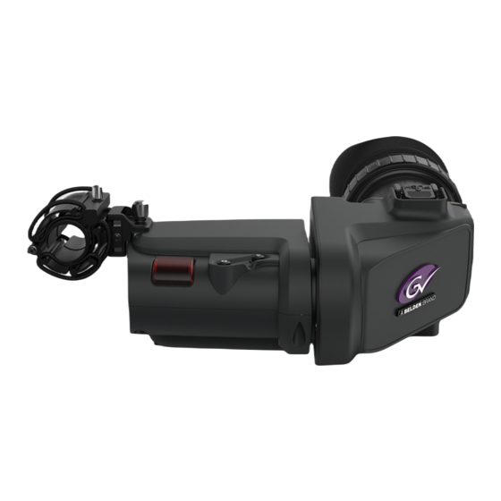
Introduction Overview The EC 2-100 is a high performance color ocular viewfinder specially designed for Grass Valley’s LDX 100 Series cameras. It is part of a line of state-of-the-art color viewfinders and is very feature-rich with an intuitive user interface. The viewfinder has a stylish look and compact design. - Page 8 Introduction Key features...
-
Page 9: Installation
Installation Mounting the viewfinder To mount the viewfinder on top of the camera adapter proceed as follows: • Loosen locking ring (2) of viewfinder support bracket (1) at the front of the camera handgrip. (As seen from the rear of the camera, turning the locking ring counterclockwise moves it towards the handgrip.) •... -
Page 10: Positioning The Viewfinder
Installation Positioning the viewfinder Positioning the viewfinder Horizontal The horizontal position of the viewfinder can be adjusted as follows to suit your preferences: • Loosen the locking ring (1). As seen from the rear of the camera, turning the locking ring counterclockwise moves it towards the handgrip. -
Page 11: Angular
EC 2-100 User’s Guide Angular Grab the viewfinder eyepiece with your hand and rotate it to the desired angle. Lateral The viewfinder can be positioned backwards and forwards along the camera axis (lateral): • Loosen the locking disc (1) by turning it counterclockwise using your thumb and index finger. - Page 12 Installation Distance viewing ☞ ☞ Note Note Handle the eyepiece with care when folded back—its position is not secured.
-
Page 13: Operation
Operation Controls Rear panel The rear panel gives access to the most important viewfinder controls. Mode Tally SW C Menu-Peak On Off Mode switch This switch determines the function of the Menu-Peak rotary control below. Set the Mode switch to the right (Peak) to adjust peaking level. Set the Mode switch to the left (Menu) to use the rotary for menu navigation. - Page 14 Operation Rear panel eyepiece. A blue border around the picture and the message “underscan” appear. Set the switch to Off to return to the original picture. Menu-Peak control When the Mode switch (1) is set to Peak, this rotary control adjusts the peaking level (sharpness) of the viewfinder picture.
-
Page 15: Front Panel
EC 2-100 User’s Guide Front panel User button A This user button can be assigned to many different functions. Refer to the section below for more details about assigning. User button B This user button can be assigned to many different functions. Refer to the section below for more details about assigning. -
Page 16: Indicators
Operation Indicators Indicators LED indicators Foc + Batt Call On Air PickMe Zoom Call On Air PickMe Gain Return indicator Lights when a return video channel is switched on in the camera. Battery power indicator Lights if the camera input voltage is too low (when using a battery). Call indicator The green LED lights to attract attention when a Call signal is activated. - Page 17 EC 2-100 User’s Guide Zoom indicator Lights when the viewfinder Zoom function is on. Focus Assist indicator Lights when the focus assist function is on (turn on in the camera menu). Range Extender indicator Lights when a range extender is selected.
-
Page 18: On Screen Indicators
Operation On screen indicators On screen indicators In the camera menu, go to the Indicators submenu to select the indicators you want to see in the viewfinder screen: F5 . 6 F:1 . 35m 16 Sf N: 0 .68m Zoom indicator Indicates the percentage to which the lens has been zoomed out or in, ranging from 0 (wide) to 99 (tele). -
Page 19: On Screen Markers
EC 2-100 User’s Guide On screen markers In the camera menu, go to the Indicators > Markers submenu to select the indicators you want to see in the viewfinder screen: Foc + Batt Call On Air PickMe Zoom Call On Air... -
Page 20: Operational Functions
Operation Operational functions Operational functions Many viewfinder functions are set up in the camera system menu and then be assigned to one of the two buttons at the front of the viewfinder. Refer to your camera user’s guide for more information on how to use the camera system menu. Mono Switches the viewfinder to monochrome mode. -
Page 21: Focus Assist
EC 2-100 User’s Guide Focus Assist The Focus Assist function adds a crawling effect in the viewfinder to objects in sharp focus. The FOC+ indicator in the viewfinder lights when this function is active. Go to the camera system menu to turn Focus Assist on or off. - Page 22 Operation Zebra...
-
Page 23: Viewfinder Setup
Viewfinder setup Menu contents Entering the menu Some specific viewfinder functions can be set up in the viewfinder menu. Enter the menu as follows: • Make sure the mode switch on the rear panel is set to Menu (left position). •... -
Page 24: Diagnostics Menu (Diag)
Viewfinder setup Diagnostics menu (DIAG) Diagnostics menu (DIAG) Item Value(s) Description EXIT DIAG Exits the diagnostics menu. STATUS INFO Enters the viewfinder status information screen. Refer to Viewfinder status information, on page 19. — — — LCD Temp nn C Info: shows the current LCD screen temperature in degrees celsius. -
Page 25: Color Menu (Color)
Viewfinder status information The status information screen shows information about the viewfinder’s internal hard- and software components. This information can be useful when contacting Grass Valley service support. Press EXIT to leave this screen. V i e w f i n d e r S t a t u s I n f o r m a t i o n... - Page 26 Viewfinder setup Viewfinder status information...
-
Page 27: Appendix A Specifications
Specifications General Dimensions (W x H x D) 206 x 76 x 219 mm (8.1 x 3.0 x 8.6 in) without microphone holder Weight (approx.) 0.90 kg (2.0 lbs) Operating temperatures -20 to +45 °C (-4 to +113 °F) Storage temperatures -25 to +70 °C (-13 to +158 °F) Power supply +10.5 to +17 VDC (supplied by the camera) -
Page 28: Dimensions
Specifications Dimensions Dimensions 97 mm 109 mm 206 mm Accessories • Microphone holder (supplied) -
Page 29: Connector
EC 2-100 User’s Guide Connector manufacturer code: Description Fischer MiniMax Series MP11ZL08 2007 USB - (I C control data) BK1 Z1AS Drain (Lane 1+2) USB +(I C control data) VF Power + VF video (Lane 1 +) VF video (Lane 1 -) - Page 30 Specifications Connector...
-
Page 31: Contact Us
1-800-547-8949 (US and Canada) or +1 530 478 4148. To obtain a local phone number for the support center nearest you, please consult the Contact Us section of Grass Valley’s website ( www.grassvalley.com An online form for e-mail contact is also available from the website.
Need help?
Do you have a question about the EC 2-100 and is the answer not in the manual?
Questions and answers