Advertisement
Quick Links
Please read all instructional literature carefully and thoroughly before starting. Refer to the final page for the listing of
Recommended Practices, Liabilities and Warrantees.
GENERAL
MISUSE OF THIS PRODUCT MAY CAUSE
EXPLOSION AND PERSONAL INJURY.
THESE INSTRUCTIONS MUST BE THOR-
OUGHLY READ AND UNDERSTOOD BEFORE
UNIT IS INSTALLED.
The 120 Series pressure and differential pressure
controls are actuated when a bellows, diaphragm or
piston sensor responds to a pressure change. This
response at a pre-determined set point(s) actuates
a SPDT, dual SPDT or DPDT snap-acting
microswitch(es), which converts the pressure signal
into an electrical signal. Control set point(s) may be
varied by turning the internal adjustment hex (J120
models) or the external knob and pointer(s) (H121,
H122, H122P models) according to the procedures
outlined below.
PROOF PRESSURE LIMITS STATED IN THE
LITERATURE AND ON NAMEPLATES MUST
NEVER BE EXCEEDED, EVEN BY SURGES IN
THE SYSTEM. OCCASIONAL OPERATION OF UNIT
UP TO MAXIMUM PRESSURE IS ACCEPTABLE (E.G.
START-UP, TESTING). CONTINUOUS OPERATION
SHOULD NOT EXCEED THE DESIGNATED OVER
RANGE PRESSURE.
Proof Pressure
The highest pressure to which a sensing element may
be occasionally operated without adversely affecting
setpoint calibration and repeatability.
Part I - Installation
MOUNTING
ALWAYS HOLD A WRENCH ON THE
PRESSURE HOUSING HEX WHEN MOUNT-
ING UNIT. DO NOT TIGHTEN BY TURNING
ENCLOSURE. THIS WILL DAMAGE SENSOR AND
WEAKEN SOLDER OR WELDED JOINTS.
INSTALL UNITS WHERE SHOCK, VIBRA-
TION AND TEMPERATURE FLUCTUATIONS
ARE MINIMAL. ORIENT UNIT TO PREVENT
MOISTURE FROM ENTERING THE ENCLOSURE.
IT IS IMPERATIVE TO USE PROPERLY RATED
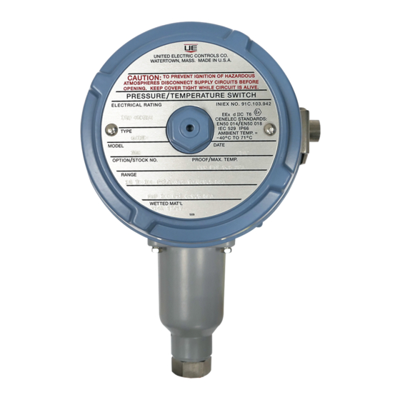
120 Series
Explosion-Proof Pressure
and Differential Pressure
Switches
UL listed, CSA Certififed,
FM approved (option M415*)
Class I, Division 1, Groups B*, C, D
Class II, Division 2, Groups E, F, G
Class III
*NOTE: CSA, Class I, Division 1, Group B does not apply
to controls with option code 1530 or M450
**Not available with M450
CENELEC approved (Prefix "Q")
EN50 014 and EN50 018
EEX d IIC T6
TOOLS NEEDED
Screwdriver
Adjustable Wrench to 1
1
⁄
"
2
U N I T E D
C O N T R O L S
Installation and Maintenance
Instructions
EXPLOSION-PROOF SEALING FITTINGS FOR ELEC-
TRICAL WIRE ENTRY. DO NOT MOUNT UNIT IN
AMBIENT TEMPERATURES LOWER THAN -40°F
(40°C) OR HIGHER THAN 160°F (71°C).
Types J120, J120K, H121, H121K, H122,
H122K, H122P
Mount controls vertically (pressure connection facing
down, See Figure 1a) or horizontally (electrical condui
facing up, See Figure 1b). Either mounting position will
Vent Holes
Breather Drain
(facing down)
Figure 1a: H121, H121K, H122,
H122K, H122P
properly orient the venting system. Control may be
surface mounted via the four 1/4" screw holes on the
enclosure or mounting bracket. It can also be mouned
directly to a rigid pipe using the pressure connection.
Types J120K, H121K, H122K Opposed Sensor
Differential Pressure Models 36-39, (S)147(B)-(S)157 (B),
367
"Opposed sensor" differential pressure controls should
be mounted with their pressure connection in the
horizontal position (See Figure 2). This will properly ori-
ent the vent holes on the pressure housing as well as
the 1/4" NPT venting conduit at the bottom of the third
compartment (standardly supplied with plastic plug.
E L E C T R I C
Potted Conduit Connection
Vent Holes
Breather Drain (facing down)
Figure 1b: J120, J120K
Potted Conduit
Connection
1/4" NPT
Vent Hole
Advertisement

Related Manuals for UE 120 Series


Summary of Contents for UE 120 Series
- Page 1 H122K, H122P UNIT IS INSTALLED. Mount controls vertically (pressure connection facing The 120 Series pressure and differential pressure down, See Figure 1a) or horizontally (electrical condui controls are actuated when a bellows, diaphragm or facing up, See Figure 1b). Either mounting position will piston sensor responds to a pressure change.
-
Page 2: Tools Needed
Controls with Breather Drain (Option M450) Remove cover and wire control (See Figure 3). Replacing cover hand tight (a minimum of 5 full Type J120, J120K Models 455-559 threads engaged) is sufficient to maintain proper protection. Additional tightening is required to fully Mount with breather drain facing down and conduit con- nection facing up (See Figure 1b). - Page 3 Option M210 J120K: Opposed Sensor, Models 36-39, 147-157, Window Mounting S147B, S157B, 367 Screw Adjust Screw Span Adjust Screw Window Plexiglass Adjust Lock Figure 5 When not set together, the front switch can not be set higher than the rear switch. Turning the external Figure 4a Figure 4b knob will increase or decrease each switch setting...
- Page 4 2) Unhook extension spring from conduit wire guide Models 680, 701-705, 356-376, 612, 616 and remove wire guide. Turn hex (IN) 3 flats from this point (approximately 3) Remove (2) microswitch mounting screws on low 1/2 turn). This will provide for a 14-16 mil gap. set microswitch and insulator.
- Page 5 Dimensions Dimension A Models Inches Pressure Internal Set Point Adjustment 126-164 8.50 215,9 S126B-S164B 8.84 244,5 Types J120, J120K 270-376 7.81 198,4 450, 452 9.69 246,1 451, 453, 454 8.94 227,0 520-525 9.06 230,2 530-535 8.56 217,4 550, 552 9.75 247,7 551, 553-555 9.31...
-
Page 6: Limited Warranty
Orient unit so that moisture does not enter the enclosure via the electrical connection. • Unit must not be altered or modified after shipment. Consult UE if modification is necessary. • Monitor operation to observe warning signs of possible damage to unit, such as drift in set point.