Table of Contents
Advertisement
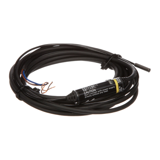
Cable Amplifier Proximity Sensor
E2EC
High-sensitivity DC 2-Wire
Sensors and Subminiature
Sensors with Long-distance
Detection
■ Shielded Sensor Heads from 3-mm to M12
diameters that can be embedded in metal.
■ Robotics cables provided as a standard feature
(DC 2-Wire Models).
■ Indicator provided in Amplifier cable for easy
confirmation of operation.
■ Power supply range of 5 to 24 VDC for DC 3-Wire
Models.
Be sure to read Safety Precautions on
page 6.
Ordering Information
Sensors
DC 2-Wire Models
Appearance
3 dia.
*
Shielded
5.4 dia.
8 dia.
*
M12
*
* Models with different frequencies are also available. The model numbers are E2EC-@@@@5 (example: E2EC-CR8D15).
DC 3-Wire Models
Appearance
3 dia.
*
Shielded
8 dia.
*
* Models with different frequencies are also available. The model numbers are E2EC-@@@@5 (example: E2EC-CR5D15).
Accessories (Order Separately)
Mounting Bracket
Appearance
Model
Y92E-F5R4
http://www.ia.omron.com/
Sensing distance
0.8 mm
*
1.5 mm
3 mm
4 mm
Sensing distance
0.5 mm
2.5 mm
Applicable Sensors
E2EC-C1R5D@ (5.4-mm-dia. Sensor)
Model
Operation mode
NO
E2EC-CR8D1
E2EC-C1R5D1
E2EC-C3D1
E2EC-X4D1
Model
Output configuration
NPN open-collector output
(c)Copyright OMRON Corporation 2007 All Rights Reserved.
NC
E2EC-CR8D2
E2EC-C1R5D2
E2EC-C3D2
E2EC-X4D2
NO
E2EC-CR5C1
E2EC-C2R5C1
1
Advertisement
Table of Contents

Related Manuals for Omron E2EC Series


Summary of Contents for Omron E2EC Series
- Page 1 8 dia. E2EC-C2R5C1 2.5 mm * Models with different frequencies are also available. The model numbers are E2EC-@@@@5 (example: E2EC-CR5D15). Accessories (Order Separately) Mounting Bracket Appearance Model Applicable Sensors Y92E-F5R4 E2EC-C1R5D@ (5.4-mm-dia. Sensor) http://www.ia.omron.com/ (c)Copyright OMRON Corporation 2007 All Rights Reserved.
-
Page 2: Ratings And Specifications
* The response frequency is an average value. Measurement conditions are as follows: standard sensing object, a distance of twice the standard sensing object, and a set distance of half the sensing distance. http://www.ia.omron.com/ (c)Copyright OMRON Corporation 2007 All Rights Reserved. -
Page 3: Engineering Data (Typical)
Distance Y (mm) Distance Y (mm) Sensing Head Sensing Head Sensing Head E2EC-X4D1 E2EC-CR5C1 E2EC-C2R5C1 -1.5 -0.5 Distance Y (mm) Distance Y (mm) Distance Y (mm) Sensing Head Sensing Head Sensing Head http://www.ia.omron.com/ (c)Copyright OMRON Corporation 2007 All Rights Reserved. - Page 4 Side length of sensing object: d (mm) Residual Output Voltage Leakage Current DC 2-Wire Models E2EC E2EC-CR8D1 E2EC-C3D1 E2EC-X4D1 E2EC-C1R5D1 30 50 300 500 1,000 Load current (mA) Power supply voltage (V) http://www.ia.omron.com/ (c)Copyright OMRON Corporation 2007 All Rights Reserved.
-
Page 5: I/O Circuit Diagrams
Not present Sensor Output main E2EC-CR5C1 Output transistor circuit E2EC-C2R5C1 (load) Blue Detection indicator (red) Maximum load current: 100 mA Note: The Sensor may be destroyed if mistakes are made in wiring. http://www.ia.omron.com/ (c)Copyright OMRON Corporation 2007 All Rights Reserved. -
Page 6: Safety Precautions
2. Press the other end of the Amplifier onto the Bracket. Cable Amplifier 2. The Amplifier will be automatically released due to the spring force of the Mounting Bracket. Mounting Bracket http://www.ia.omron.com/ (c)Copyright OMRON Corporation 2007 All Rights Reserved. -
Page 7: Main Units
Setting indicator (green) Two, 3.2-dia. mounting holes D2 Models: Operation indicator (red) Mounting Bracket Mounting Hole Dimensions Model F (mm) +0.3 E2EC-CR8D@ dia. +0.3 E2EC-C1R5D@ dia. +0.5 E2EC-C3D@ dia. +0.5 E2EC-X4D@ 12.5 dia. http://www.ia.omron.com/ (c)Copyright OMRON Corporation 2007 All Rights Reserved. - Page 8 Two, R1.6 Material: Stainless steel (SUS301) Note: Provided with DC 2-Wire Models. 34.5± Accessories (Order Separately) Mounting Bracket (for 5.4 dia.) R2.6 Y92E-F5R4 Material: Stainless steel (SUS304) Note: Used for E2EC-C1R5D@ Head. http://www.ia.omron.com/ (c)Copyright OMRON Corporation 2007 All Rights Reserved.
-
Page 9: General Precautions
Brown Sensor Brown − Blue Sensor Blue ●Operating Environment Do not use the Sensor in an environment where there are explosive or combustible gases. http://www.ia.omron.com/ (c)Copyright OMRON Corporation 2007 All Rights Reserved. - Page 10 Other con- Cost feasibility: Price/delivery time Life: Power-ON time/frequency of use siderations * mT (millitesla) is a unit for expressing magnetic flux density. One tesla is the equivalent of 10,000 gauss. http://www.ia.omron.com/ (c)Copyright OMRON Corporation 2007 All Rights Reserved.
- Page 11 A Sensor is ready for detection within 100 ms after turning ON the power. If the load and Sensor are connected to separate power supplies, design the system so that the Sensor power turns ON first. http://www.ia.omron.com/ (c)Copyright OMRON Corporation 2007 All Rights Reserved.
- Page 12 It is recommend that leeway be included in the actual values used. For 12 VDC, use 15 kΩ or less and 450 mW or higher, and for 24 VDC, use 30 kΩ or less and 0.1 W or higher. http://www.ia.omron.com/ (c)Copyright OMRON Corporation 2007 All Rights Reserved.
- Page 13 Bracket, first secure the Amplifier Unit to the special Mounting Bracket, and then mount the special Mounting Bracket with M3 screws and flat washers with a diameter of 6 mm maximum. Flat washers (6 dia. max.) http://www.ia.omron.com/ (c)Copyright OMRON Corporation 2007 All Rights Reserved.
- Page 14 Note: When AND/OR connections are used with Proximity Sensors, the effects of erroneous pulses or leakage current may prevent use. Verify that there are no problems before use. http://www.ia.omron.com/ (c)Copyright OMRON Corporation 2007 All Rights Reserved.
- Page 15 (Same for DC models.) DC 3-Wire Sensors Operation can be reversed with the signal input switch on the S3D2. Blue 0 V Black OUT Brown +12 V S3D2 http://www.ia.omron.com/ (c)Copyright OMRON Corporation 2007 All Rights Reserved.
- Page 16 Do not under any circumstances attempt to disassemble or repair the product. Quick Failure Check You can conveniently check for failures by connecting the E39-VA Handy Checker to check the operation of the Sensor. http://www.ia.omron.com/ (c)Copyright OMRON Corporation 2007 All Rights Reserved.
- Page 17 Warranty and Limitations of Liability WARRANTY OMRON's exclusive warranty is that the products are free from defects in materials and workmanship for a period of one year (or other period if specifi ed) from date of sale by OMRON. OMRON MAKES NO WARRANTY OR REPRESENTATION, EXPRESS OR IMPLIED, REGARDING NON-INFRINGEMENT, MERCHANTABILITY, OR FITNESS FOR PARTICULAR PURPOSE OF THE PRODUCTS.
Need help?
Do you have a question about the E2EC Series and is the answer not in the manual?
Questions and answers