Page 1
HDMI Encoder/Decoder NJR-P01U Series NJR-P01UF-T/NJR-P01UF-R 
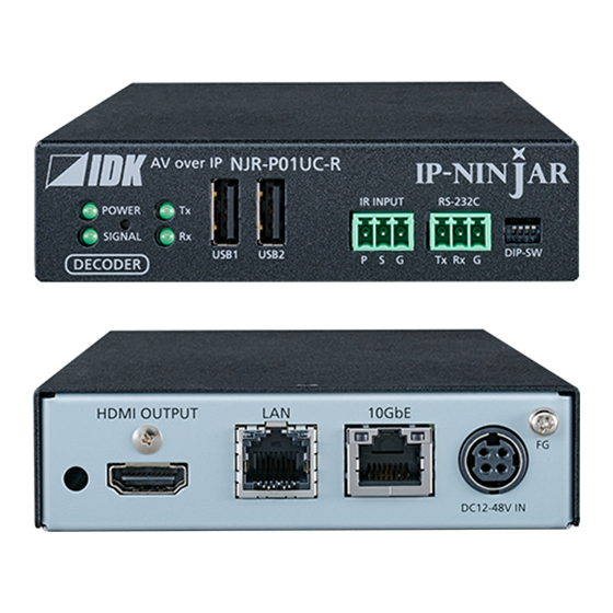
NJR-P01UC-T/NJR-P01UC-R <User Guide> Ver.1.0.0 Thank you for choosing our product. To ensure the best performance of this product, please read this user guide fully and carefully before using it and keep this manual together with the product for future reference as needed.
Page 2
HDMI Licensing Administrator, Inc. in the United States and other countries. Connection Reset and IP-NINJAR are registered trademarks of IDK Corporation in Japan. All other company and product names mentioned in this manual are either registered trademarks or...
Page 3
NJR-P01U Series User Guide Before reading this manual All rights reserved. Some information contained in this User guide such as exact product appearance, diagrams, menu operations, and so on may differ depending on the product version. This User g website at: http://www.idkav.com...
Page 4
NJR-P01U Series User Guide Safety Instructions Read and understand all safety and operating instructions before using this product. Follow all instructions and heed all warnings/cautions. Enforcement Symbol Description Indicates the presence of a hazard that may result in death or serious personal injury if the warning is ignored or the product is handled incorrectly.
Page 5
Do not repair, modify or disassemble. Since the product includes circuitry that uses potentially lethal, high voltage levels, disassembly by unauthorized personnel may lead to the risk of fire or electric shock. For internal inspection or repair, contact your IDK Do not representative.
Page 6
Unplug immediately if the product is damaged by falling or having been dropped. If you continue to use the product under these conditions, it may increase the risk of electrical shock or fire. For maintenance and repair, contact your IDK representative. Unplug Unplug immediately if water or other objects are directed inside.
Page 7
NJR-P01U Series User Guide For installing and connecting products: Do not place the product in a location where it will be subjected to high temperatures. If the product is subjected to direct sunlight or high temperatures while under operation, it may affect the product s performance and reliability and may increase the risk of fire.
NJR-P01U Series User Guide This user guide explains how to use the NJR-P01UF/NJR-P01UC ( NJR- about external control through the IP-NINJAR Configurator and NJR-CTB. The NJR-P01UF-T/NJR-P01UC-T is an encoder while the NJR-P01UF-R/NJR-P01UC-R is a decoder. If other IP-NINJAR series products are connected, refer to each User Guide.
NJR-P01U Series User Guide Ensure all items below are included in the package. If any items are missing or damaged, please contact IDK. NJR-P01UF/C-T NJR-P01UF/C-R SFP+ optical transceiver DIN plug AC adapter with locking Cable clamp mechanism (4 ft. (1.2 m))
NJR-P01U Series User Guide The MM/SM model (NJR-P01UF-T/R-MM/SM) has an SFP+ optical transceiver that is vulnerable to damage caused by mishandling during shipment if it is improperly packaged. If, for any reason, you need to ship the device, remove the transceiver from the device and plug the dust cap into the transceiver and the connector.
NJR-P01U Series User Guide The NJR-P is an AV over IP solution for high definition signal transmission via fiber optic cables or category cables. This 4K solution leverages 10 Gb Ethernet switches and enables signal management of 4K@60 (4:4:4) signals with zero latency. USB HID class is also supported for KVM extension application. Additionally, via the NJR-P, the NJR-CTB can be controlled using an IR cable (IR-P01-R) and recommended remote controller.
Page 14
NJR-P01U Series User Guide Video Up to 4K@60 (4:4:4) HDCP 1.4/2.2 Transmission distances Fiber optic cable (NJR-P01UF-T-MM/SM, NJR-P01UF-R-MM/SM) Multimode fiber (OM3) : Up to 984 ft. (300 m) Singlemode fiber (OS1) : Up to 6.21 mi. (10 km) (Up to 24.85 mi. (40 km, optional))
Page 15
NJR-P01U Series User Guide NJR-P01UF-T NJR-P01UF-T-MM NJR-P01UF-T-SM NJR-P01UC-T Up to 16 ft. (5 m) Video/Audio D Receiver Digital video/audio Input HDMI DVI EDID emulator Video Scan Multimode fiber (OM3) : Up to 984 ft. (300 m) converter Singlemode fiber (OS1) : Up to 6.21 mi.
NJR-P01U Series User Guide 6.1 NJR-P01U-T (Encoder) 6.1.1 NJR-P01UF-T (Fiber optic model) [Fig. 6.1] NJR-P01UF-T drawing [Table 6.1] NJR-P01UF-T features Feature Description HDMI input connector Input connectors for HDMI signal to connect to a source devices, such as Blu-ray players HDMI cable fixing hole Fixes HDMI cables by inserting provided cable clamps.
Page 17
NJR-P01U Series User Guide [Table 6.2] NJR-P01UF-T features (Cont d) Feature Description LEDs (green) POWER : Illuminates when power is supplied from the AC adapter. SIGNAL : Illuminates when video signals are valid; blinks when video signals cannot be transmitted correctly.
NJR-P01U Series User Guide 6.1.2 NJR-P01UC-T (CAT model) [Fig. 6.2] NJR-P01UC-T drawing [Table 6.3] NJR-P01UC-T features Feature Description HDMI input connector Input connectors for HDMI signal to connect to a source devices, such as Blu-ray players HDMI cable fixing hole Fixes HDMI cables by inserting provided cable clamps.
Page 19
NJR-P01U Series User Guide [Table 6.4] NJR-P01UC-T features (Cont d) Feature Description LEDs (green) POWER : Illuminates when power is supplied from the AC adapter. SIGNAL : Illuminates when video signals are valid; blinks when video signals cannot be transmitted correctly.
NJR-P01U Series User Guide 6.2 NJR-P01U-R (Decoder) 6.2.1 NJR-P01UF-R (Fiber optic model) [Fig. 6.3] NJR-P01UF-R drawing [Table 6.5] NJR-P01UF-R features Feature Description HDMI output connector Output connector for HDMI signals Connects to a sink device, such as an LCD monitor.
Page 21
NJR-P01U Series User Guide [Table 6.6] NJR-P01UF-R features (Cont d) Feature Description LEDs (green) POWER : Illuminates when power is supplied from the AC adapter. SIGNAL : Illuminates when video signals are valid; blinks when video signals cannot be transmitted correctly.
NJR-P01U Series User Guide 6.2.2 NJR-P01UC-R (CAT model) [Fig. 6.4] NJR-P01UC-R drawing [Table 6.7] NJR-P01UC-R features Feature Description HDMI output connector Output connector for HDMI signals Connects to a sink device, such as an LCD monitor. HDMI cable fixing hole Fixes HDMI cables by inserting provided cable clamps.
Page 23
NJR-P01U Series User Guide [Table 6.8] NJR-P01UC-R features (Cont d) Feature Description LEDs (green) POWER : Illuminates when power is supplied from the AC adapter. SIGNAL : Illuminates when video signals are valid; blinks when video signals cannot be transmitted correctly.
NJR-P01U Series User Guide This chapter cites two system configuration examples. 7.1 Used as Network Extender Using the NJR-P and other IP-NINJAR encoders/decoders with a 10 GbE switch enables extending, distributing, matrix switching, videowall, and multiview. Video and audio signals are input from the Blu-ray player to the HDMI input connector of NJR-P01UF-T /NJR-T04HD.
NJR-P01U Series User Guide 7.2 Used as Extender The NJR-P and other IP-NINJAR encoders/decoders are connected as Point To Point. Video and audio signals are input from the Blu-ray player to the HDMI input connector of NJR-P01UF/C-T /NJR-T04HD. NJR-P01UF/C-T/NJR-T04HD sends these signals to NJR-P01UF/C-R/NJR-R04HD over a fiber optic cable or category cable.
Page 26
NJR-P01U Series User Guide Multiview using NJR-T04HD and NJR-P01UF-R HDMI/DVI Up to 98 ft. (30 m) 1080p Blu-ray player HDMI/DVI 1080p Up to 16 ft. (5 m) Blu-ray player NJR-T04HD NJR-P01UF-R 4K monitor 4K@60 1080p Maximum transmission distances Blu-ray player Multimode fiber (OM3) : 984 ft.
(1.2 in. (30 mm) or more) When the NJR-P needs to be mounted in an enclosed space or an EIA rack without using IDK s rack mounting hardware, ensure that a sufficient ventilation/cooling system is provided to keep the ambient temperature at 104°...
NJR-P01U Series User Guide 8.3 Cabling When connecting the NJR-P to external devices, please observe the following precautions. Read manuals for the external devices. Before connecting cables to the NJR-P or an external device, dissipate static electricity by touching grounded metal such as equipment racks before handling signal cables. Failure to observe this precaution may result in ESD (electrostatic discharge) damage.
NJR-P01U Series User Guide 8.3.1 HDMI cable When the video is 4K format, the maximum TMDS data rate (transmission speed) is 18 Gbps. If a high-speed HDMI cable is used, the maximum TMDS data rate of 10.2 Gbps can be transferred, and the video cannot be displayed stably.
NJR-P01U Series User Guide 8.3.2 Fiber optic cable for extension The NJR-P can reach their full potential by selecting appropriate fiber optic cables for long-haul extension and installing the cable correctly. Connect the output connector of this device to the input connector of the target device.
NJR-P01U Series User Guide To polish connectors: For SFP+ optical transceiver for multimode : PC polishing is recommended. For SFP+ optical transceiver for singlemode : UPC polishing is recommended. Note: APC polishing is not supported. Transmission distance varies depending on attenuation of the fiber, connector and other contact portions.
NJR-P01U Series User Guide 8.3.4 Category cable for extension To ensure the best performance of category cables, select a correct category cable and connect it correctly. Cat6A is recommended for optimal performance. If using an STP cable, connect the FG connector to a ground source. Otherwise, the shielding feature does not work correctly.
NJR-P01U Series User Guide 8.3.6 Connecting LAN cable Pin assignment of the LAN connector is as follows. Auto MDI/MDI-X that detecting and switching straight cable/cross cable is supported. 8-pin RJ-45 Modular connector Signal name Pin No. MDI-X 1000BASE-T 100BASE-TX/10BASE-T 1000BASE-T 100BASE-TX/10BASE-T TRX+ (Transmitted &...
NJR-P01U Series User Guide 8.3.7 Connecting USB To enable USB HID communication, connect cables as follows: Connect Connect the USB connecters of the decoder to a USB HID keyboard and mouse. Notes: Only HID class is supported. USB products other than HID class (USB hub, gaming mouse/keyboard, hub-integrated keyboard, and the like) are not supported.
NJR-P01U Series User Guide 8.3.9 Supplying power NJR-P01UC-T/R can be powered from PoE-supported 10 GbE switch (IEEE 802.3at/IEEE 802.3af) or DIN plug AC adapter. Powered by PoE-supported 10 GbE switch Before connecting a category cable, ensure that AC adapter is not connected. Refer to the manual of 10 GbE switch for power supply.
Page 36
NJR-P01U Series User Guide Plugging and unplugging DC plug Plug the DC plug to the power supply connector of the unit until it clicks. Hold the portion mentioned below when unplugging the DC plug. Hold this part and pull the DC plug.
NJR-P01U Series User Guide 8.4 Setting DIP switch Use the DIP switch to change settings of NJR-P. Settings for NJR-P01UF/C-T Description Selects internal connection of the RS-232C connector. OFF : Connects to IP-NINJAR decoders. ON : Connects to the CPU and sets settings of NJR-P01UF/C-T.
NJR-P01U Series User Guide NJR-P can be set from commands over RS-232C communication and NJR-CTB or IP-NINJAR Configurator. PC for control PC for control PC for control (For communication (For communication (For IP-NINJAR Configurator) command) command) RS-232C RS-232C Cable for extension...
NJR-P01U Series User Guide 9.1 Control over RS-232C communication The NJR-P can be controlled over RS-232C communication. You can control NJR-P and get its status by connecting a control unit, such as PCs, to NJR-P over an RS-232C cable. The RS-232C connector has two modes: control mode is controlling NJR-P01UF/C-T or NJR-P01UF/C-R and communication mode is communicating between peripheral devices connected to NJR-P01UF/C-T or NJR-P01UF/C-R.
NJR-P01U Series User Guide 9.2 Controlled by IP-NINJAR Configurator The NJR-P connected to LAN can be set from the IP-NINJAR Configurator remotely over LAN communication. The following settings can be set from the GUI: setting RS-232C, setting LAN, resetting settings, and rebooting NJR-P.
NJR-P01U Series User Guide 9.3 Controlled by NJR-CTB The NJR-CTB is the integrated control unit for IP-NINJARs connected to a network over a 10 GbE switch. The control box can control all devices and acquire their statuses using communication commands through WEB browser or LAN by connecting to NJR-P or 10 GbE switch.
NJR-P01U Series User Guide 9.4 Setting Items Some setting items can be controlled through commands/GUI operation; the others cannot be controlled. [Table 9.1] Setting items Command: Command input, GUI: GUI operation, WEB&C: WEB browser and command input, No: Not supported...
NJR-P01U Series User Guide 9.5 Initialization You can initialize settings to factory defaults using IP-NINJAR Configurator or NJR-CTB via LAN communication. When initialization completes, NJR-P reboots with new settings automatically. Note: Once values are initialized, they cannot be restored. See: 9.2 Controlled by IP-NINJAR Configurator See: 9.3 Controlled by NJR-CTB...
NJR-P01U Series User Guide The following items of NJR-P can be set using the RS-232C communication, IP-NINJAR Configurator, or NJR-CTB. In this manual, only settings of NJR-P are explained. Refer to NJR-CTB User Guide for the following operations: Using as Network Extender base on 10GbE Switcher, setting channel information, selecting input/output channel, operating preset memory, setting videowall, setting crosspoint, and setting NJR-CTB LAN.
NJR-P01U Series User Guide 10.1 Input 10.1.1 Non-signal input monitoring NJR-P01UF/C-T If EDID of the encoder is changed or it is turned ON/OFF, the source device may not output video signal. In this case, you can set the time length which is from when a source device stops outputting signal to when the encoder requests the source device to output video signal.
NJR-P01U Series User Guide 10.1.2 HDCP input enabled/disabled NJR-P01UF/C-T Some source devices negotiate with the connected device to determine if HDCP encryption is supported. After this negotiation, the source device determines whether HDCP signal encryption is enforced or not. This process takes place with some source device, even if the content being presented is not copyright protected.
NJR-P01U Series User Guide 10.2 Output 10.2.1 Output mode NJR-P01UF/C-T/R You can set the color space to be sent to the sink device. The sink device selects the best color space for the color space of the input video automatically, but if for some reason the sink device cannot select the color space, set the desired color space in encoder or decoder.
NJR-P01U Series User Guide NJR-P01UF/C-R 10.2.3 Hot plug ignoring duration Time for ignoring the video output request signals sent from the sink device. If the request signals are repeated in a short cycle, the NJR-P processes video output from the first cycle.
NJR-P01U Series User Guide 10.3 Audio 10.3.1 Muting digital audio NJR-P01UF/C-T/R You can enable or disable the audio output mute. Once you mute encoder, all audio of decoder connected through the 10 GbE switch can be muted. When you mute decoder, output audio from the HDMI output connector of decoder is muted.
NJR-P01U Series User Guide 10.4 EDID 10.4.1 EDID resolution NJR-P01UF/C-T You can set the desired resolution that is output from the source device. Setting value [Table 10.2] Maximum resolution of EDID Max. resolution Pixel Standard Remarks Copied EDID If no acquired data, 2160p (50/59.94/60, 4:4:4) 1080p (50/59.94/60)
Page 51
NJR-P01U Series User Guide Notes: For 4096×2160: The source device may select 3840×2160 (30p, YCbCr 4:4:4) depending on the EDID definition. First set built-in EDID and then select 4096×2160 in the source device side. For YCbCr4:2:0: The source device may select 3840×2160 (30p, YCbCr 4:4:4) depending on the EDID definition.
NJR-P01U Series User Guide 10.4.2 Copying EDID NJR-P01UF/C-T You can load and register EDID of the sink device that is connected to an NJR decoder. The copied EDID can be treated in the same way as the internal EDID. In order to copy the EDID of the sink device connected to an NJR decoder, set this item from the IP-NINJAR Configurator or NJR-CTB.
NJR-P01U Series User Guide 10.4.4 Deep Color NJR-P01UF/C-T You can set the color depth that is output from the source device. Setting value 24-BIT COLOR [Default] 30-BIT COLOR 36-BIT COLOR Note: If you select , the transmission clock speed increases. Noise may occur if a bad-quality cable or long cable is connected.
NJR-P01U Series User Guide 10.4.6 Speaker configuration NJR-P01UF/C-T You can set the speaker configuration of multi-channel audio. Once changing the number of speaker, the configuration is automatically set as follows. You can change the default configuration, and you can also set each speaker individually Setting value [Table 10.5] Default speaker configuration...
NJR-P01U Series User Guide 10.6 RS-232C 10.6.1 RS-232C communication NJR-P01UF/C-T/R You can set the RS-232C communication between devices that connected to encoder/decoder. The same setting should be set for encoder/decoder. Notes: The RS-232C connector is used for two modes: controlling encoder or decoder and communicating between devices that connected to encoder/decoder.
NJR-P01U Series User Guide 10.7 LAN 10.7.1 LAN NJR-P01UF/C-T/R The IP address can be obtained automatically by DHCP (Dynamic Host Configuration Protocol). Static IP address, subnet mask, and default gateway can also be configured manually. Setting value [Table 10.7] LAN setting items...
NJR-P01U Series User Guide 10.8 Information 10.8.1 Input status NJR-P01UF/C-T You can display the signal status that is input from the HDMI input connector. Information to be displayed [Table 10.9] Input signals Value Description HDMI signal is input. xx stands for color depth which is 24, 30, or 36.
NJR-P01U Series User Guide 10.8.2 Output status NJR-P01UF/C-R You can display the status of the sink device connected to the HDMI output connector. Information to be displayed [Table 10.13] HDCP authentication status Value Description HDCP 1.4 SUPPORT Authenticated with HDCP 1.4 HDCP 2.2 SUPPORT...
NJR-P01U Series User Guide 10.8.3 Monitor EDID NJR-P01UF/C-R You can display the EDID of the sink device connected to the HDMI output connector. Information to be displayed [Table 10.16] Displayed value Displayed value Example Remarks Monitor name NJR-P01UF-T If no monitor is connected,...
NJR-P01U Series User Guide 10.8.4 Version NJR-P01UF/C-T/R You can display the model number and firmware version. Information to be displayed [Table 10.17] Version Item Example Model number NJR-P01UF-T Firmware version 1.00...
NJR-P01U Series User Guide 11.1 NJR-P01UF-T/R Item NJR-P01UF-T (Encoder) NJR-P01UF-R (Decoder) 1 input 1 input HDMI/DVI 1.0 Digital signal for extension TMDS single link Format: IP-NINJAR protocol HDCP 1.4/2.2 RS-232C/LAN/USB Input HDR (*1) Connector: 2 LC x.v.Color/3D/ARC/HEC/CEC are not supported.
NJR-P01U Series User Guide 11.2 NJR-P01UC-T/R Item NJR-P01UC-T (Encoder) NJR-P01UC-R (Decoder) 1 input 1 input HDMI/DVI 1.0 Digital signal for extension TMDS single link Format: IP-NINJAR protocol HDCP 1.4/2.2 RS-232C/LAN/USB Input HDR (*1) PoE power supplied (PD) x.v.Color/3D/ARC/HEC/CEC are not supported.
NJR-P01U Series User Guide In case the NJR-P does not work correctly, please check the following items first. Also refer to manuals for connected devices as well, since they may possibly be the cause of the problem. Are the NJR-P and all devices connected to power and powered on?
Page 64
NJR-P01U Series User Guide User Guide of NJR-P01U Series Ver.1.0.0 Issued on: 1 October 2020 Headquarters IDK Corporation 7-9-1 Chuo, Yamato-shi, Kanagawa-pref. 242-0021 JAPAN TEL: +81-46-200-0764 FAX: +81-46-200-0765 Email: idk_eng@idk.co.jp URL: http://www.idkav.com IDK America Inc. 72 Grays Bridge Road Suite 1-C, Brookfield, CT 06804 TEL: +1-203-204-2445 Email: sales@idkav.com...
Need help?
Do you have a question about the NJR-P01U Series and is the answer not in the manual?
Questions and answers