Gree LIVV09HP230V1A Series Service & Parts Manual
Hide thumbs
Also See for LIVV09HP230V1A Series:
- Quick start manual (2 pages) ,
- Installation manual (33 pages)


Need help?
Do you have a question about the LIVV09HP230V1A Series and is the answer not in the manual?
Questions and answers
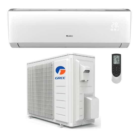
(My remote is model: YAN1F10F and split unit is model: LIVV09HP230V1AH) I don’t know what the fan-looking symbol is above the temp# and below the fan. (See picture) How do I turn that off? (My guest turned it on, I assume. I don’t recall it being there before.)
To turn off the fan-looking symbol on the Gree LIVV09HP230V1AH split unit using the YAN1F10F remote, press the FAN button. This cycles through fan speed settings, and selecting the appropriate mode (like AUTO or COOL) may remove the standalone fan symbol if it's currently in FAN-only mode.
This answer is automatically generated
@Mr. Anderson thank you. When that symbol is present on the Facebook the remote, meaning FAN-only as you stated, does it mean the A/C is not working,, I.e. only the fan is operating?