Advertisement
Quick Links
INSTALLATION INSTRUCTIONS
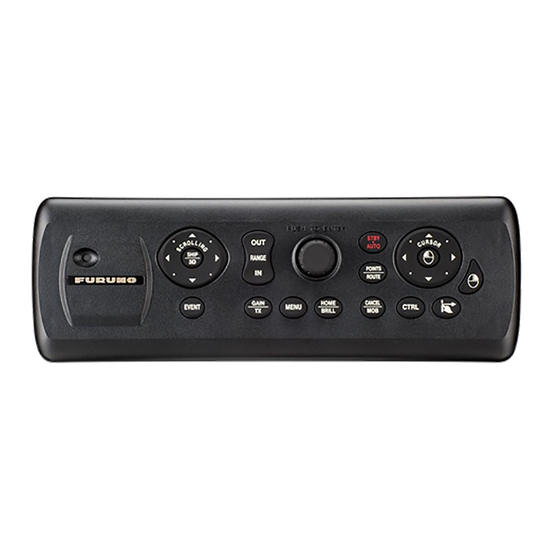
MCU-005 CONTROL UNIT
The following installation instructions cover how to install the MCU-005 Control Unit.
Before installation, check the notes below regarding running of the cables.
The MCU-005 is designed to be flush-mounted in a console or panel.
Note regarding running of the cables
To reduce stress on the connectors, prevent accidental disconnection and also to prevent water
intrusion, make sure that the wiring at the rear of the control unit meets the following recommen-
dations.
• Cables should not be run upwards from the units. Make sure the cable are run downwards.
• Cables should be bundled together with sufficient slack to allow service and maintenance.
• Bundled cables should be secured in a manner that prevents stress on the connectors, caused
by heave and pitch.
The figures below show examples of cabling, along with the above recommendations.
MCU-005
Cables should not be routed in
a way that allows moisture or
water to drip into the unit.
Packing list
MCU-005 MODIFICATION KIT (Type: OP19-19, Code: 001-506-900)
Part name
CONTROL UNIT
PANEL REMOVER
LAN CABLE ASSEMBLY
PACKING BB
SELF TAPPING SCREW
FLUSH MOUTNING TEMPLATE
Note: "*" indicates revision/version number.
Other
MCU-005
equipment
Cables should not be hung
freely. This causes stress
on the connectors and may
cause disconnections.
Type
MCU-005
19-028-3124
MOD-Z072-050+
19-028-1581
4x20 SUS304
C42-00703-*
www.furuno.com
MCU-005
Cables should be bundled
with a wire-tie and secured
against the inside of the
console or to a bulkhead.
There should be enough
slack in the cables to allow
service and maintenance.
Code
Amount
100-340-471-10
001-167-890-10
100-340-742-10
000-158-850-10
000-167-223-1*
Other
equipment
1
1
1
1
4
1
Advertisement

Related Manuals for Furuno MCU-005


Summary of Contents for Furuno MCU-005
- Page 1 INSTALLATION INSTRUCTIONS MCU-005 CONTROL UNIT The following installation instructions cover how to install the MCU-005 Control Unit. Before installation, check the notes below regarding running of the cables. The MCU-005 is designed to be flush-mounted in a console or panel.
-
Page 2: Installation Procedure
Installation procedure Referring to the flushmount template, included with the MCU-005, prepare a cutout at the mounting location. Referring to the figure below, remove the front panel of the control unit. Note: The catches should be unfastened in the indicated numerical order to prevent damage or breakage. - Page 3 Attach the front panel to the control unit. Console/desktop After the NavNet TZtouch2/NavNet TZtouch3 is powered and ready for use, press the CTRL key on the MCU-005. The control unit is now ready for use with the NavNet TZtouch2/NavNet TZtouch3.
- Page 4 How to remove the front panel after installation You may need to remove the front panel for maintenance or service. To remove the front panel, follow the procedure below. Take care that each step is followed correctly to prevent damage to the equipment.
- Page 5 D-1...
- Page 6 This page is intentionally left blank.
- Page 7 こ のページは空白です。...
- Page 8 こ のページは空白です。...
- Page 9 では前面パネルを取 り 外 さ ないで く だ さ い。 MCU-005 の左下の溝に、 パネル リ ムーバーを差 し 込みます。 パネル リ ムーバーを倒 し て、 前面パネルを少 し 持ち上げます。 同 じ 要領で、 MCU-005 右下の溝にパネル リ ムーバーを差 し 込んで持ち上げます。 前面パネル左右にで き た空間に、 パネル リ ムーバーを差 し 込んで持ち上げます。 (両側で行っ て く だ さ い。)...
- Page 10 取付け穴に MCU-005 をはめ込みます。 注) ケーブルが挟まれたり、潰れたりしていないことを確認してください。 支給の ト ラ ス タ ッ ピ ン ネジ 4 本 (φ4X20) を使 っ て、 MCU-005 を取付け穴に固定 し ます。 前面パネルを元に戻 し ます。 NavNet TZtouch2/NavNet TZtouch3 起動後、 MCU-005 の [CTRL] キーを押 し ます。 MCU-005 が使用できるようになります。...
- Page 11 装備手順 支給の型紙を使 っ て、 装備位置に取付け穴を開けます。 MCU-005 にあ る ツ メ (合計 6 ヵ 所) を下図の番号順に手で外 し て、 前面パネルを外 し ます。 注) ツメの部分は、嵌合がきつくなっています。前面パネルが割れないよう注意して、取り外して ください。 MCU-005 の背面に、 支給のスポン ジ を貼 り 付けます。 MCU-005 の背面にあ る NETWORK お よびアース端子に、 支給の LAN ケーブル組品 と アース線 (IV-...
- Page 12 ケーブル引回 し に関する注意事項 コ ネ ク タ 部に掛か る 負担を軽減 し 、 ケーブルの本体 と の接続が外れた り 、 水が本体内部に侵入 す る こ と を防ぐ ために、 MCU-005 のケーブルが、 以下の よ う に配線 さ れてい る こ と を確認 し て く だ さ い。...
Need help?
Do you have a question about the MCU-005 and is the answer not in the manual?
Questions and answers