Advertisement
Quick Links
Installation and Operation Instructions
CCD CAMERA WAT-704R
Your reading through and understanding of the following "IMPORTANT" are much appreciated before use.
Important:
1. USE ONLY +9.0~+9.9V DC POWER SOURCE WITH CORRECT POLARITY.
2. FOR INDOOR USE ONLY, DO NOT ALLOW THE WAT-704R CAMERA TO GET WET.
3. DO NOT DROP OR STRIKE THE WAT-704R CAMERA.
4. DO NOT OPEN CAMERA. There are no serviceable parts inside the camera and opening it will void all warranties.
Attempting to repair or change circuit, or applying incorrect power to circuits will damage the camera and void the
warranty.
5. Aiming the camera toward spotlighted areas, areas of high contrast or intense light MAY CAUSE SMEARING on the
monitor image and never aim the camera directly to the sun.
6. Camera is equipped with electronic iris shutter circuit, therefore use under fluorescent or incandesent lamp MAY CAUSE
FLICKERING to occur on monitor image.
7. NEVER CONNECT THE WAT-704R CAMERA TO A ONE LINE SYSTEM WHICH SUPPLIES DIRECT CURRENT
TO THE VIDEO SIGNAL TERMINAL. DOING SO WILL DESTROY THE CAMERA!
Carefully read All instructions before connecting the WAT-704R Camera to monitor.
8. Be sure not to apply AC,DC power source to the VIDEO OUT cable (white) of the WAT-704R.
9. Operating instructions should be read carefuy prior to connecting power source.
10. If camera does not work properly, review soldering instructions to insure proper operation.
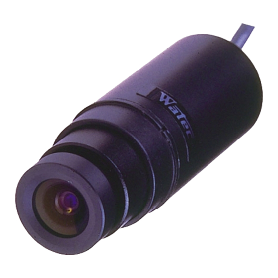
Structure:
Installation:
Before installation of the WAT-704R check all power supplies of your system turned off.
1) Connect power source and video output as shown in the following figure.
Fig. 2 WAT-704R Output codes
Please protect the soldering connection with Tape, Tube, and etc..
Red White Black
Fig. 3 How to connect the codes
①Lens
Upper ①:Type G-3.8
Lower ①:Type P-3.7
②WAT-704R
③Instalation Ring
④Screw ( M2.6
8mm )
×
⑤Nut ( M2.6 )
Fig. 1
Red
: DC+9.0~9.9v
White : Video Out
Black : Common GND
DC +9.0~9.9v
Common GND
75Ω Coaxial Cable
Monitor
Only connect to a DC+9.0~9.9V over 150mA power source of correct
polarity. Especially, higher voltage (over DC+9.9V) will make the
WAT-704R damaged.
Check if your own power supply will be corresponded to the left circuit
diagram, when it is arranged by yourself.
Use the "HEAT SINK" according to your selected voltage
regurator.
When extension of the cable required,be sure to use the core line tarminated at 75 ohm for the white line of the WAT-704R.
Be sure to use the sealed (outer brass) line of the WAT-704R.
When extension of the cable required, be sure to use the cable of 3C2V or 5C2V terminated at 75 ohm.
And also when a CRT display monitor required, be sure to tarminate the cable with an inpedance of 75 ohm.
2) Fixing the Ring, Screw and Nut on the WAT-704R.
Set the Instalation Ring.
(Set only this part.)
Fig. 4
Passing way of the Ring over the lens.
The WAT-704R housing is of aluminium, the intense shock may cause the housing distorted.
Be careful of the WAT-704R housing on installation, accordingly. (When the WAT-704R housing is distorted, it may
induce the "SHORT - CIRCUIT", leading to a breakage.
3) Turn on all the power supplies for the WAT-704R and Monitor.
Turn off all the power supplies immediately, when the WAT-704R does not work properly.
And review the connections of the power source and video out.
If any question or further information on power supply and /or video out is requierd, please contact your
dealer whitch you have purchased the WAT-704R.
4) Focus on while looking at the monitor.
Bring into focus by turning the lens clockwise or counter-clock
wise. Focussing adjustment of the pin-hole lens (type : P-3.7) can
be done by turning the lens clockwise or counter-clockwise while
placing a pair of tweezers in the focussing adjustment dent as
shown in the left fig. 6.
Be careful to make focussing adjustment not so as
to scratch the lens on the surface.
DC +9v
VOLTAGE
Red
REGURATOR
Black
Circuit Diagram of Regulated Power Supply
There is a small slit ( Upper side mark ).
Do not set the Ring at this part.
Fig. 5
Fixing position of the Ring.
Dimples for lens
focussing
adjustment.
Fig. 6
Front view of type P-3.7
Advertisement

Subscribe to Our Youtube Channel
Related Manuals for Watec WAT-704R Series


Summary of Contents for Watec WAT-704R Series
- Page 1 Installation and Operation Instructions Only connect to a DC+9.0~9.9V over 150mA power source of correct polarity. Especially, higher voltage (over DC+9.9V) will make the DC +9v VOLTAGE WAT-704R damaged. REGURATOR CCD CAMERA WAT-704R Check if your own power supply will be corresponded to the left circuit diagram, when it is arranged by yourself.
- Page 2 Please direct further enquiries to the local dealer where you purchased your WAT-704R camera. Address : 254-2, Nihonkoku, Daihoji, Tsuruoka-Shi, Yamagata-Ken, 997-0017 JAPAN. Phone : +81-235-23-4400 Fax : +81-235-23-4409 http://www.watec.net E-mail : info@watec.net ( Model G-3.8 ) (Model P-3.7) Watec Co.,Ltd. Front View Side View of type P-3.7...
Need help?
Do you have a question about the WAT-704R Series and is the answer not in the manual?
Questions and answers