
Related Manuals for Absen LR3.9-7.8


Summary of Contents for Absen LR3.9-7.8
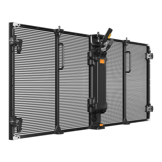
- Page 1 LR3.9-7.8 User Manual High transparency Lightweight Fast operation Curved design High refresh rate...
-
Page 2: Table Of Contents
4.4 Receive Card Maintenance ......................- 21 - 4.4.1 Receive card maintenance steps ..................- 21 - 4.5 Hub Maintenance ..........................- 22 - 5. Flight Case ..............................- 22 - 6. Common Faults and troubleshooting ......................- 23 - - 2 - LR3.9-7.8 User Manual... -
Page 3: Safety Information
Please read this manual carefully before installing, powering up, operating and maintenance of this product. Follow safety instructions in this manual and on the product. If you have any questions, please seek help from Absen. Beware of Electric Shock! • To prevent electric shock the device must be properly grounded during installation. Do ignore using the grounding plug, or else there is a risk of electric shock. - Page 4 • Any component that has a recycling bin label can be recycled. • For more information on collecting, reusing and recycling, please contact the local or regional waste management unit. • Please contact us directly for detailed environmental performance information. - 4 - LR3.9-7.8 User Manual...
-
Page 5: 1.Product Introduction
1.1 Product Main Features • The transparency of LR3.9-7.8 is as high as 50%, which can create a mysterious stage effect. • LR3.9-7.8 has thin panel and hollowed-out PCB, which can bring the advantage of light weight, making operation and movement more convenient. -
Page 6: Product Specifications
1.2 Product Specifications Parameters LR3.9-7.8 LED Type SMD1921 Pixel Pitch (mm) Horizontal 3.9 - Vertical 7.8 Cabinet Pixels 256*64 Pixel Density (Pixels / m 34544 Module size (L × W)/(mm) 500*250 Panel size (L × W × H)/(mm) 1000*500*77.2 Physical... -
Page 7: Cabinet
1.3 Cabinet 1.3.1 Cabinet dimension figure 1.3.2 Cabinet structure description 1.4 Module 1.4.1 Module dimension figure - 7 - LR3.9-7.8 User Manual... -
Page 8: Features Of Module
• Industrial-grade waterproof socket to make more stable, and the fast elastic plug which can make usage and maintenance more convenience. 1.5 Power Supply 1.5.1 Power Output characteristics Output Voltage Regulation Min. Current Rated Current +4.5V ±5% - 8 - LR3.9-7.8 User Manual... -
Page 9: Power Input Characteristics
The A5S receiving card is connected to the Hub board through the card slot. Meanwhile, the Hub board which plays the role of transit is also connected to the module, power supply and data cable. - 9 - LR3.9-7.8 User Manual... -
Page 10: 2.Product Installation
• The installation site temperature should be -20 ℃ ~ 50 ℃, and the panels with special low temperature materials can be installed at -30 ℃ ~ 20 ℃. 2.2 Cabinets Splicing 2.2.1 Splicing horizontally 2.2.2 Splicing vertically - 10 - LR3.9-7.8 User Manual... -
Page 11: 90-Degree Splicing
2.2.3 Curve and Convex Splicing Note: LR3.9-7.8 supports curve form -15 degree to +15 degree by adjusting the arc lock to create multiple splicing effect. 2.2.4 90-degree Splicing Note: 90-degree splicing screen fixed by right angle connector. - 11 - LR3.9-7.8... -
Page 12: Hanging Installation
Step 1, Fix the hanging bars on the truss with wire rope, and connect the hanging bars horizontally with block. Step 2, Use the vertical connectors to fix the first row cabinets to the locking tabs of the hanging bars. Vertical connectors - 12 - LR3.9-7.8 User Manual... - Page 13 Step 4, Install other cabinets from top to bottom: First, align the connection holes of upper and lower cabinet; Then, let the connector tab to the left; After that, push the bolt of the vertical connector into the hole; Last, fasten the connector by turning its tab to right. - 13 - LR3.9-7.8 User Manual...
- Page 14 Let the tab to the right Push the bolt and turn its tab to the right Step 5, Connect the power cables and the network cables between the cabinets. Note: Maximum number of installations: 20 - 14 - LR3.9-7.8 User Manual...
-
Page 15: Fixed Installation
2.3 Fixed Installation 2.3.1 Preparation for fixed installation Note: Absen only offer connector block and connector plates for fixed installation if customer needs. 2.3.2 Fixed installation steps Step 1, Fixing the cabinets by connector block. Step 2, Connect the cabinets to the steel structure by connector plates. - Page 16 Connector block Connector plate 40*40Steel structure - 16 - LR3.9-7.8 User Manual...
-
Page 17: 3.Product Cabling
Network cable routing: The signal cables are connected from left to right. Please calculate the resolution according to the pixels of each cabinet. Note that the maximum load of a single network port does not exceed 650,000 pixels. - 17 - LR3.9-7.8 User Manual... -
Page 18: Wring Diagram
Fix the connecting piece Adjustable of the box and tighten wrench the M10 * 60 bolt Disassembly module & Phillips power supply & List screwdriver receiving card & adaptor plate Measuring power lines multimeter and distribution boxes - 18 - LR3.9-7.8 User Manual... -
Page 19: Module Maintenance
Measuring structure 4.2 Module Maintenance The modules of LR3.9-7.8 support rear maintenance only. 4.2.1 Module maintenance steps Step 1, Remove power box from panel by loosening four buckles. Step 2, Loosen the fixing screws of the module with a cross screwdriver, then take out the module from panel. -
Page 20: Power Supply Maintenance
To avoid module damage, please pay attention to force evenly when remove the module. 4.3 Power Supply Maintenance The power supply of LR3.9-7.8 supports rear maintenance only. 4.3.1 Power supply maintenance steps Step 1, Open the four buckles of the power box. -
Page 21: Receive Card Maintenance
Please distinguish between live, neutral, and ground, 5V positive and negative power cables. 4.4 Receive Card Maintenance The receive card of LR3.9-7.8 supports rear maintenance only. 4.4.1 Receive card maintenance steps Step 1, Remove the power box of the cabinet, please refer to 4.3 for more specific operations. -
Page 22: Hub Maintenance
4.5 Hub Maintenance The Hub card of LR3.9-7.8 supports rear maintenance only. Please refer to the maintenance method of the receiving card, then remove the fixing screw which are marked with red circle when maintaining Hub card. 5. Flight Case Flight case of LR3.9-7.8 is 6 in 1. -
Page 23: Common Faults And Troubleshooting
3. Replace the power supply; modules 4. Replace the module; 5. Replace the receiving card; All panels display 1. Set the screen connection on software; the same content 2. Check whether the data port is wrong. - 23 - LR3.9-7.8 User Manual... - Page 24 3. Check the output window of the video processor; All rights reserved by Shenzhen Absen Optoelectronic Co., Ltd. Shenzhen Absen Optoelectronic Co., Ltd. reserves the rights to modify contents without any further notice. Shenzhen Absen Optoelectronic Co., Ltd. 18-20F Building 3A, Cloud Park, Bantian, Longgang District, Shenzhen 518129, P.R.China T: +86-755-89747399 absen@absen.com...
Need help?
Do you have a question about the LR3.9-7.8 and is the answer not in the manual?
Questions and answers