Table of Contents
Advertisement
Advertisement
Table of Contents

Related Manuals for Absen 3.0 C110


Summary of Contents for Absen 3.0 C110
- Page 1 Absenicon3.0 Series C110 User Manual...
-
Page 2: Table Of Contents
Absenicon3.0 C110 User Manual Catalogue Safety Information ...........................................3 1. Product introduction ..........................................7 1.1 Product features ........................................8 1.2 Product specification......................................10 1.3 Screen Dimension Figure (mm) ..................................11 1.4 standard packaging ......................................11 2. Product Installation.......................................... 13 2.1 Installation guide ........................................13 2.2 Installation method of moving .................................. -
Page 3: Safety Information
Follow safety instructions in this manual and on the product. If you have any questions, please seek help from Absen. Beware of Electric Shock! • To prevent electric shock the device must be properly grounded during installation, Do not ignore using the grounding plug, or else there is a risk of electric shock. - Page 4 Absenicon3.0 C110 User Manual • The main power switch should be installed at a location near the product and should be clearly visible and easily reached. This way in case of any failure the power can be promptly disconnected. • Before using this product check all electrical distribution equipment, cables and all connected devices, and make sure all meet current requirements.
- Page 5 Absenicon3.0 C110 User Manual Product Disposal • Any component that has a recycling bin label can be recycled. • For more information on collecting, reusing and recycling, please contact the local or regional waste management unit. • Please contact us directly for detailed environmental performance information.
- Page 6 Absenicon3.0 C110 User Manual Warning: Changes or modifications to this unit not expressly approved by the party responsible for compliance could void the user’s authority to operate the equipment. NOTE: This equipment has been tested and found to comply with the limits for a Class A digital device, pursuant to part 15 of the FCC Rules.
-
Page 7: Product Introduction
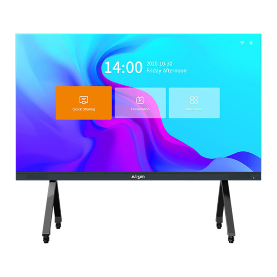
1. Product introduction Absenicon3.0 series standard conference screen is an LED intelligent conference terminal product developed by Absen, which integrates document display, high-definition display and video conference application, and can meet the multi-scene requirements of enterprise high- end conference rooms, lecture halls, lecture room, exhibitions and so on. -
Page 8: Product Features
Absenicon3.0 C110 User Manual 1.1 Product features 1. The front of the screen adopts an integrated minimalist design, and the ultra-high percentage of display area for 94%. The front of the screen has no redundant design except for the switch button and the commonly used USB*2 interface. The giant screen interacts, breaking the space boundary, and immersing the experience;... - Page 9 Absenicon3.0 C110 User Manual 14. Provide 4 scene modes, whether it is document presentation, video playback, remote meeting, can match the best display effect, so that every moment can enjoy comfort, built- in a variety of VIP welcome templates, quickly and efficiently improve the welcome atmosphere;...
-
Page 10: Product Specification
Absenicon3.0 C110 User Manual 1.2 Product specification 项目 型号 Absenicon3.0 C110 Product size (Inch) Display area(mm) 2440*1372 Screen size(mm) 2450×1487×28.5 Display Pixel Per Panel(Dots) 1920x1080 Parameters Brightness(nit) 350nit Contrast Ratio 4000:1 colour space NTSC 110% power supply AC 100-240V Power average power consumption(w) Parameters Maximum power consumption(w) -
Page 11: Screen Dimension Figure (Mm)
Absenicon3.0 C110 User Manual 1.3 Screen Dimension Figure (mm) Front view 1.4 Standard packaging The product packaging of the all-in-one machine is mainly composed of three parts: box/module packaging (1*4 modular packaging) , installation structure packaging (movable bracket or wall hanging + edging). The cabinet packaging is unified to 2010*870*500mm Three 1*4 cabinets + free packaging into honeycomb box, overall size: 2010*870*500mm... - Page 12 Absenicon3.0 C110 User Manual one 1*4 cabinet and four 4*1*4 module packages and edge into the honeycomb box, dimensions: 2010*870*500mm Installation structure packaging figure (take the movable bracket as an example)
-
Page 13: Product Installation
Absenicon3.0 C110 User Manual 2. Product Installation This product can realize wall-mounted installation and movable bracket installation. 2.1 Installation guide This product is calibrated by the whole machine. In order to ensure the best display effect, it is recommended to install it according to the identification sequence number of our company. Diagram of installation number (front view) Number description: The first digit is the screen number, the second digit is the cabinet number, from top to bottom, the... -
Page 14: Install Support Legs
Absenicon3.0 C110 User Manual with the front facing upwards (the side with the silk-printed logo on the beam is the front); Assemble the four sides of the frame, including two beams, two vertical beams and 8 M8 screws. The side of the beam with screw holes is facing up vertical beam The vertical beam has a gap on the side facing inward 2.2.2 Install support legs... -
Page 15: Install Cabinet
Absenicon3.0 C110 User Manual The front of the frame is in the same direction as the front of the support leg, and a total of 6 M8 screws on both sides are installed. 2.2.3 Install cabinet Hang the middle row of cabinet first, and hook connecting plate on the back of the cabinet into the notch of the cross beam of the frame. - Page 16 Absenicon3.0 C110 User Manual Install 4 M4 safety screws after the cabinet is installed; Note: The internal structure is subject to the actual product. Hang the cabinets on the left and right sides in turn, and lock the left and right connecting bolts on the cabinet.
-
Page 17: Install Edging
Absenicon3.0 C110 User Manual 2.2.4 Install edging Install the edging under the screen, and tighten the fixing screws of the left and right connecting plates of the bottom edging (16 M3 flat head screws); Left and right connecting plate Fix the lower edging to the bottom row of cabinets, tighten 6 M6 screws, and connect the power and signal wires of the lower edging and the bottom cabinet;... -
Page 18: Install Module
Absenicon3.0 C110 User Manual Note: The internal structure is subject to the actual product. 2.2.5 Install module Install the modules in order of number. -
Page 19: Installation Method Of Wall-Mounted
Absenicon3.0 C110 User Manual 2.3 Installation method of wall-mounted 2.3.1 Assemble frame Take out the frame from the packing box, including the cross beam and vertical beam. Place it on the ground with the front facing upwards (the side with the silk-printed logo on the beam is the front); Assemble the four sides of the frame, including two beams, two vertical beams and 8 M8 screws. -
Page 20: Install Frame Fixed Connecting Plate
Absenicon3.0 C110 User Manual 2.3.2 Install frame fixed connecting plate Install the frame fixed connecting plate; After the connecting plate is installed, install the back frame, and fix it with 2 Frame fixed connecting plate M6*16 screws at each position (the screws are topped into the groove on the (Each is fixed with 3 M8 expansion screws)... -
Page 21: Install Cabinet
Absenicon3.0 C110 User Manual 2.3.4 Install cabinet Hang the middle row of cabinet first, and hook connecting plate on the back of the cabinet into the notch of the cross beam of the frame. Move the cabinet to the center and align the marking line on the beam; Hook connecting plate Flat connecting plate Install 4 M4 safety screws after the cabinet is installed;... -
Page 22: Install Edging
Absenicon3.0 C110 User Manual Cabinet safety screws Hook connecting plate cross beam Note: The internal structure is subject to the actual product. Hang the cabinets on the left and right sides in turn, and lock the left and right connecting bolts on the cabinet. The four-corner hook connecting plate of the screen are flat connecting plate. - Page 23 Absenicon3.0 C110 User Manual left and right connecting plates of edging Fix the lower edging to the bottom row of cabinets, tighten 6 M6 screws, and connect the power and signal wires of the lower edging and the bottom cabinet; Note: The internal structure is subject to the actual product.
-
Page 24: Install Module
Absenicon3.0 C110 User Manual Note: The internal structure is subject to the actual product. 2.3.6 Install module Install the modules in order of number. Please refer to Absenicon3.0 C138 user manual for system operation instructions and maintenance instructions...
Need help?
Do you have a question about the 3.0 C110 and is the answer not in the manual?
Questions and answers